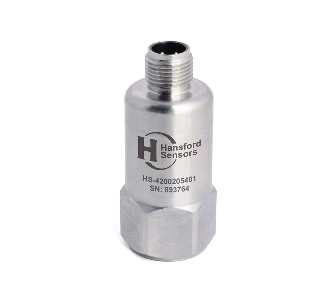
HS-420 4–20 mA vibration sensor (velocity), top exit, M12 connector
- 4–20 mA
- Top exit
- IP68
- M12
PDF datasheet
Exclusive Hansford Sensors distributor for Poland, the Czech Republic and Slovakia
In the rail industry, a failure of a rolling stock component or trackside equipment means delays, a vehicle taken out of service and sometimes a risk to operational safety. Vibration measurement helps assess the condition of traction motors, gearboxes and bearings and make better use of the time vehicles spend in the depot.

Rolling stock availability determines whether the timetable can be delivered, and every vehicle withdrawn from service because of an unexpected fault means cost and disruption to vehicle rotations. Inspections and repairs are carried out according to the maintenance system documentation; information on the condition of traction motors, gearboxes or fans helps to prepare the scope of work better and to catch faults that develop between inspections.
On a vehicle, the sensor operates under strong shocks from rail joints and turnouts, over a wide temperature range, in water, snow and brake dust — and in the depot, in the train wash as well. Cables must be protected against ballast impacts and abrasion, and the measurement chain must be immune to interference from traction drives and converters.
Trackside equipment is dispersed and operates unattended, so a simple signal that can be sent to a local controller and on to a supervisory system is useful. In repair workshops, vibration measurement is used to assess motors and gearboxes on test benches after repair.
01Machines in this industry
Traction motors, gearboxes and drivetrains, wheelset bearings and others — measuring point on the bearing housing.
02Sensor
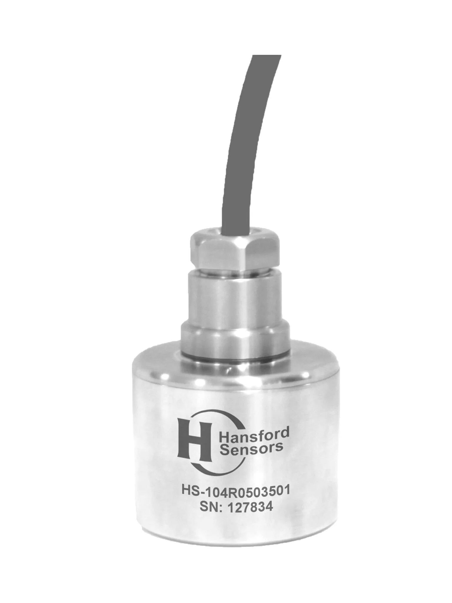
An IEPE accelerometer or a 4–20 mA sensor converts vibration (and often temperature) into an electrical signal.
Industrial IEPE accelerometers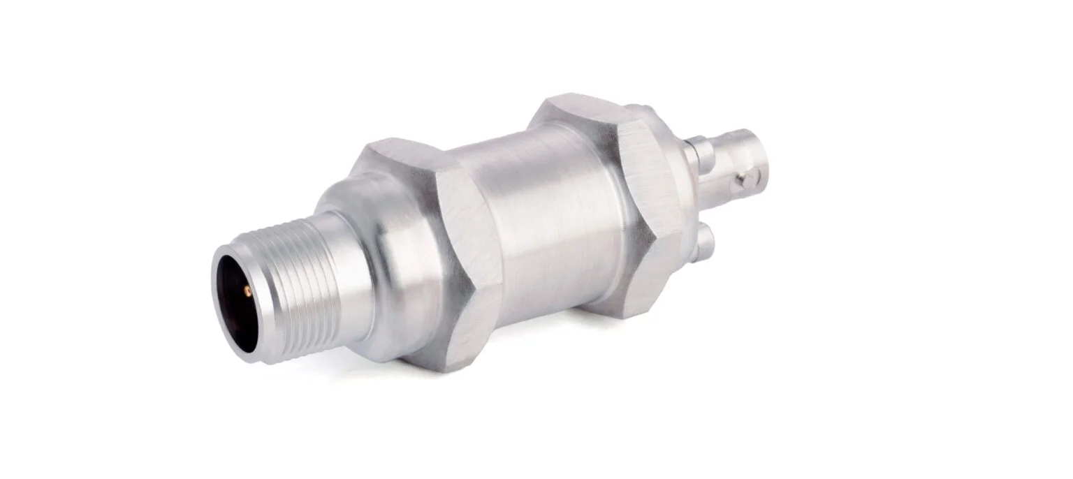
03Signal
A cable with the right connector and a junction box carry the signal from many measuring points to the system.
Cables and connectors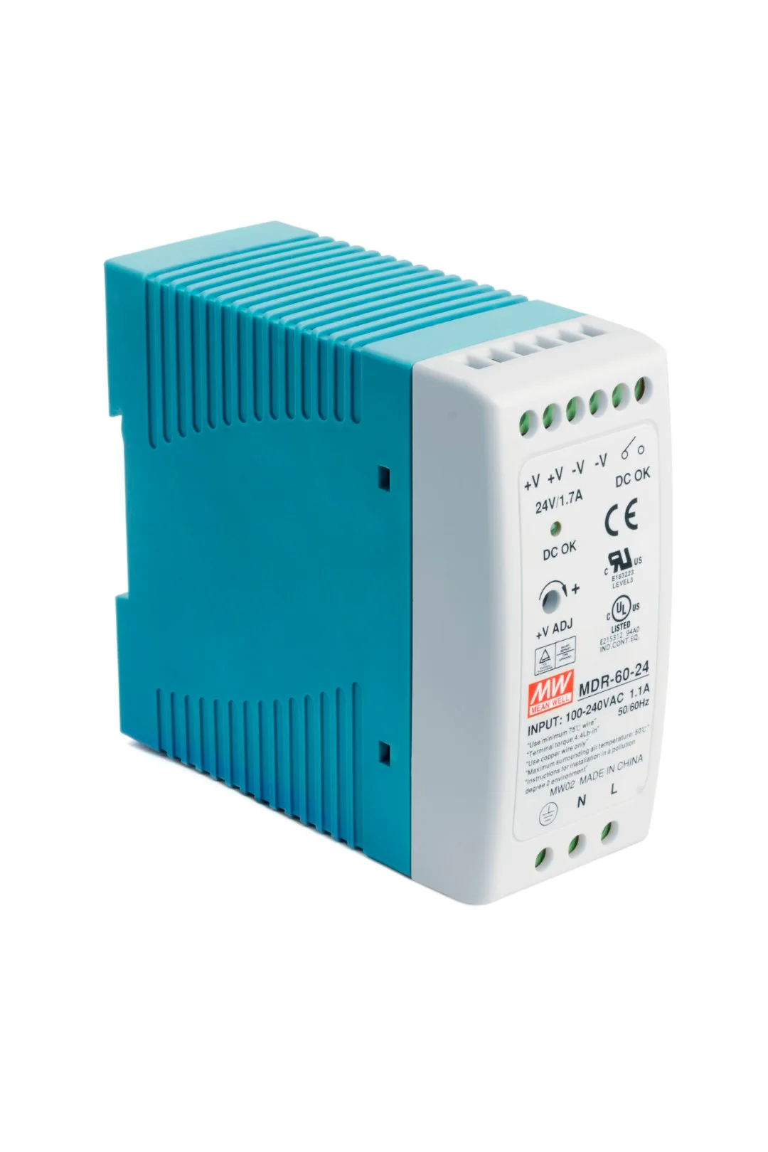
04Monitoring
PLC, DCS, an online system or a data collector: trends, alarm thresholds and diagnostics before a failure happens.
Vibration systems and switchesThe HS-100 AC accelerometer, with a standard sensitivity of 100 mV/g, provides a signal for spectrum analysis, which can identify bearing damage, gear tooth wear or rotor unbalance in a traction motor. The signal can go to an on-board diagnostic system or be collected with a data collector while the vehicle is at the depot. See industrial accelerometers.
HS-420 sends a 4–20 mA signal proportional to vibration velocity directly to on-board and trackside PLCs. It is a simple solution for continuous trending and alarms on fans, pumps and auxiliary machines, including at unattended sites — see 4–20 mA vibration sensors.
Mount the sensor on a stud, with the thread secured against loosening — under continuous shocks, a magnetic mount does not provide a lasting fixing.
Route the cable along the structure and secure it with clamps, protecting it from ballast, water and abrasion; where materials with a reduced fire hazard are required, check the properties of the selected cable.
Isolating studs separate the sensor housing from the structure and help to avoid earth loops — see sensor mounting hardware.
Protect connections and reading points by placing them in boxes from the industrial enclosures category.
On a test bench for a traction motor or gearbox after repair, an HS-100 accelerometer on a magnetic mount allows quick measurements at several points and in several directions. Comparison with results from units in good condition reveals unbalance, bearing damage and assembly errors before the component goes back into the vehicle.
PDF datasheet
4–20 mA sensor for on-board and trackside PLC systems.
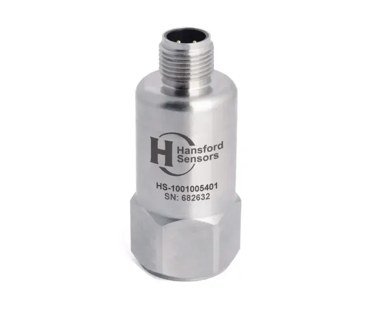
PDF datasheet
AC accelerometer for traction motors, gearboxes and bearings.
It depends on the mounting location. Unsprung components such as axleboxes are subject to very strong shocks, so the sensor’s measuring range and shock resistance must be compared with the operating conditions, using the datasheet. Rail vehicles are also subject to project requirements and railway standards, which should be checked before choosing a model.
Measurements are taken on the end shields in the radial and axial directions, at a defined rotational speed. The spectrum is compared with results from known-good units or with in-house acceptance values. This makes it possible to detect unbalance, bearing damage and assembly errors. An AC accelerometer on a magnetic mount and a data collector are sufficient for these measurements.
For continuous monitoring, the simplest option is a 4–20 mA transmitter such as the HS-420, connected to a local controller that passes the trend and alarms to the supervisory system. If you also need to diagnose causes, the AC signal can additionally be brought out to a connection box, and periodic measurements taken with a data collector during service visits.
Describe the component or equipment, the mounting location and the project requirements: standards, cables, connectors. We will help you select a sensor and check what documentation is available for it.