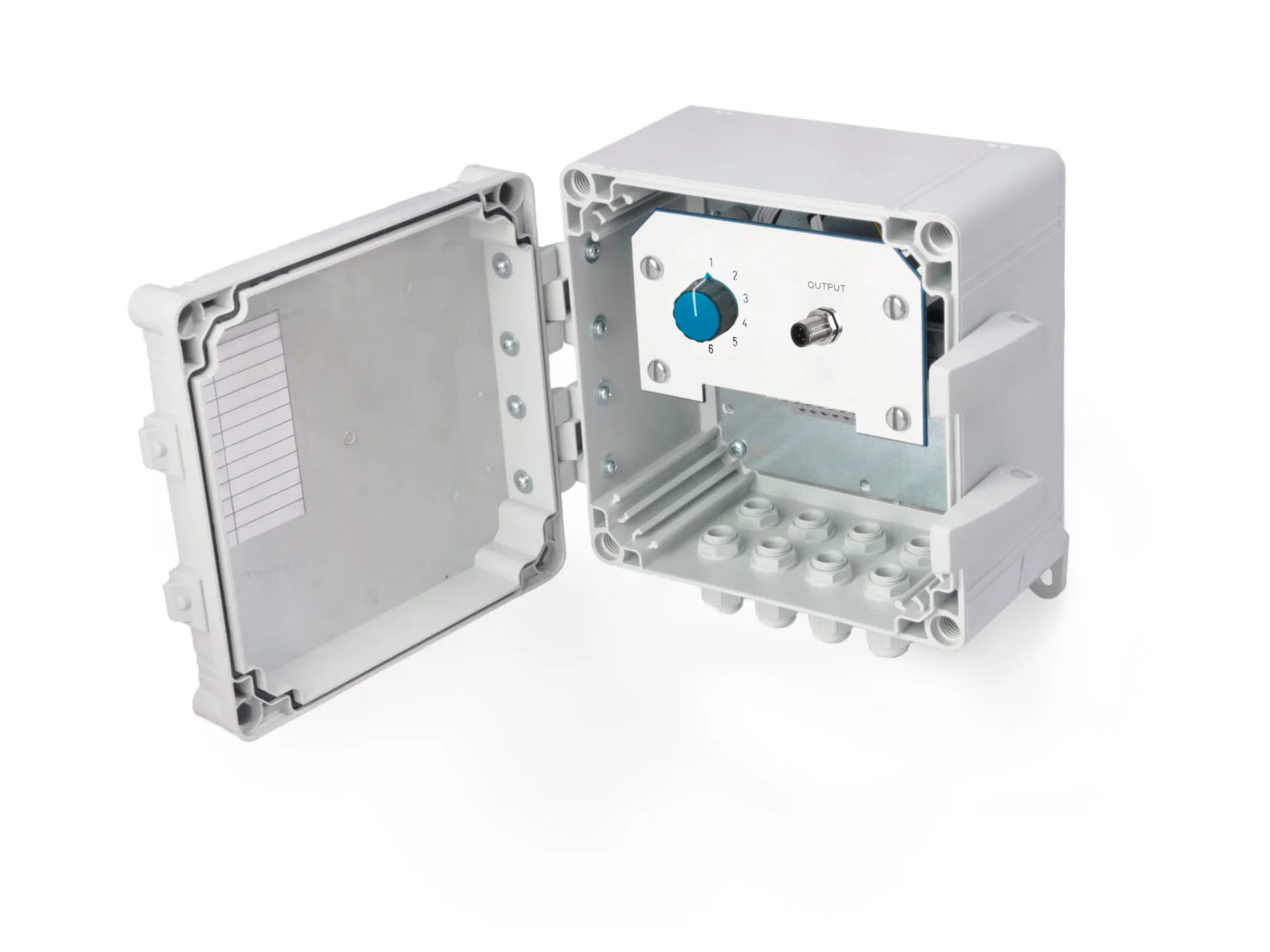
HS-SE-TX-PC HS-SE series Polycarbonate switch box for triaxial sensors
- IP66
- 3 axes
PDF datasheet
Exclusive Hansford Sensors distributor for Poland, the Czech Republic and Slovakia
In metallurgical plants, rolling mills and metal processing facilities, machines work cyclically, under heavy and often shock loads, and close to hot material. Vibration measurement makes it possible to detect bearing wear, misalignment and looseness in the drives of rolling mills, presses and fans at an early stage — before a failure stops the entire production line.

Metallurgical lines are tightly coupled: stopping one mill stand, shear or furnace fan halts the entire production line. An unplanned stop is not just lost production — the heated stock cools down and may need reheating, and a damaged bearing in a rolling mill gearbox can destroy the gear teeth and shafts in a short time. Spare parts for large drives are often made to order, so early fault detection gives time to prepare the repair and is the basis of predictive maintenance.
Sensors work in dust and mill scale, exposed to cooling water and emulsion, and under radiant heat from furnaces and hot material. In addition, there are shocks as material passes through the stands and during press and shear operation, as well as electromagnetic interference from high-power drives. This requires robust housings, careful cable selection and routing the cables away from power cables.
The machinery is very diverse — from low-speed rolls and roller tables to high-speed fans and pumps. This is why a single plant usually combines different sensor types and different strategies: periodic measurements, continuous monitoring in the PLC and local machine protection.
01Machines in this industry
Mill stands and rolling mill gearboxes, rolls and roller tables, presses, shears and cutting lines and others — measuring point on the bearing housing.
02Sensor
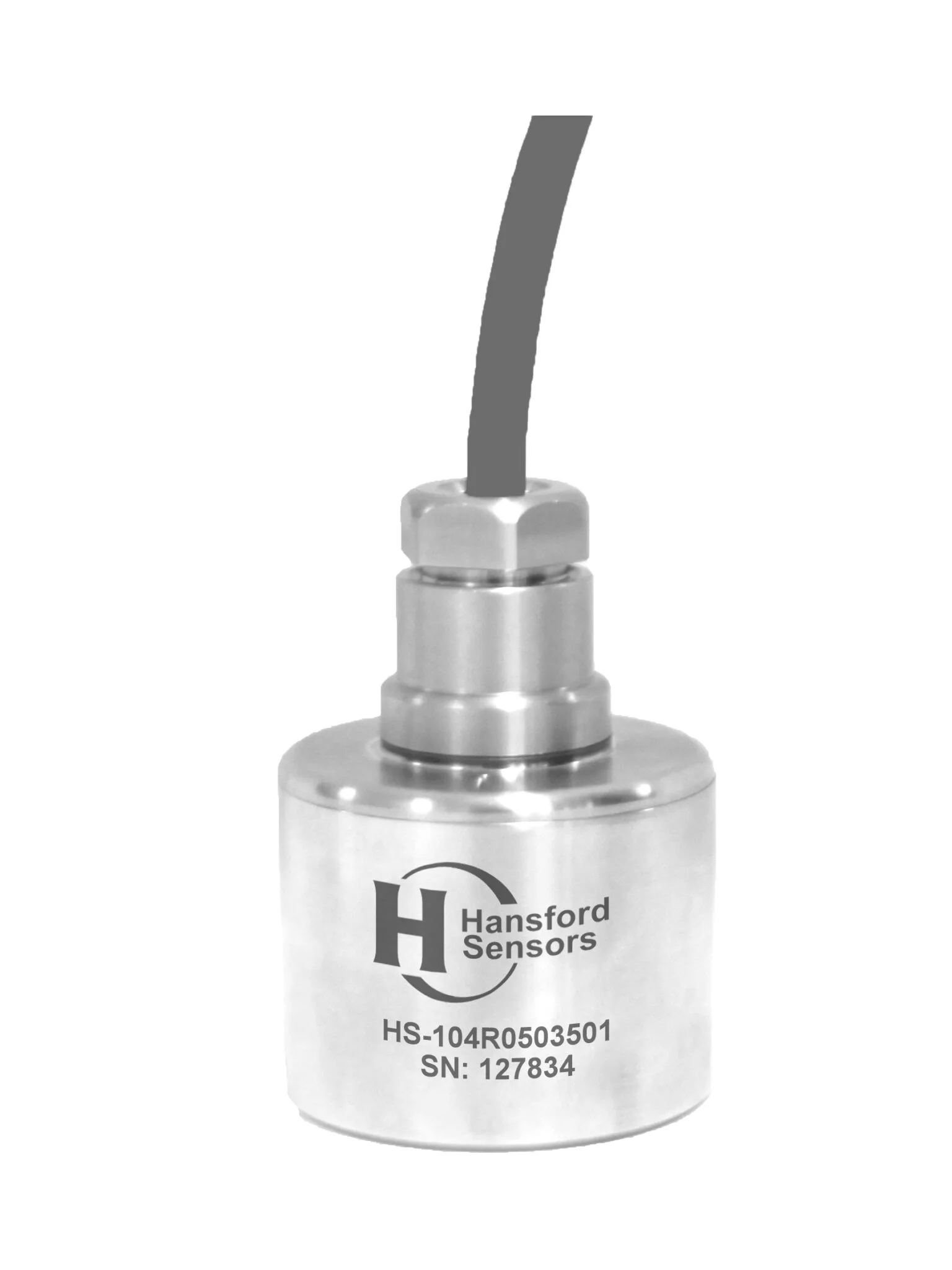
An IEPE accelerometer or a 4–20 mA sensor converts vibration (and often temperature) into an electrical signal.
Industrial IEPE accelerometers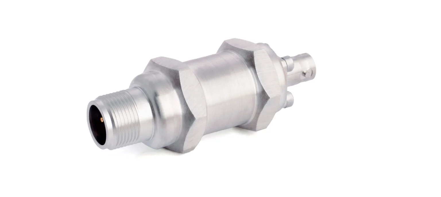
03Signal
A cable with the right connector and a junction box carry the signal from many measuring points to the system.
Cables and connectors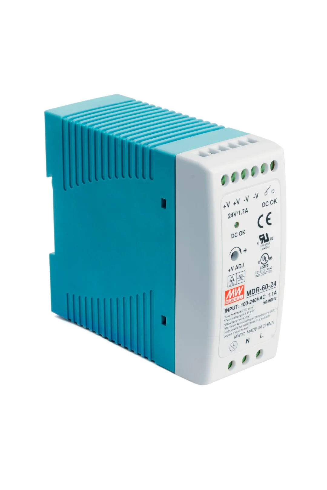
04Monitoring
PLC, DCS, an online system or a data collector: trends, alarm thresholds and diagnostics before a failure happens.
Vibration systems and switchesA vibration diagnostics programme is usually based on HS-100 — a stainless steel AC accelerometer with a standard sensitivity of 100 mV/g. A sensor permanently mounted at the bearing and cabled to an HS-SE switch box allows route measurements to be taken with a data collector from one safe location — without removing guards and without coming within reach of the line’s moving parts. The same sensor can also supply a signal to an online monitoring system if the machine requires continuous analysis.
Where a continuous trend matters more than detailed analysis — on fans, pumps and auxiliary motors — HS-420 works well. The sensor provides a 4–20 mA signal proportional to vibration velocity, which goes directly to an analogue input of a PLC or SCADA system. This makes it possible to record trends and generate alarms when thresholds are exceeded, but it does not replace spectrum analysis: an AC signal is needed to find the cause of increased vibration. You will find the full range in the 4–20 mA vibration sensors category.
Machines that need on-site protection can be fitted with AC accelerometers working with HS-500 series vibration modules. The modules can display the vibration level and signal alarms locally, while also passing the signal to the PLC. The functions of individual modules differ, so compare their datasheets in the vibration systems and switches category.
At low rotational speeds, bearing fault signals are weak and lie in the low-frequency range. For such machines, the manufacturer offers HS-100F — a filtered version with a response matched to low-frequency measurements — as well as AC accelerometers with higher sensitivity. The standard frequency range of AC accelerometers is 0.8 Hz – 15 kHz (±3 dB) and can be adjusted with filters; the frequency range and sensitivity of a specific version are given in its datasheet.
According to the manufacturer, HS-100 operates at up to 150 °C, but the permissible temperature of a specific version also depends on the cable and connector — check it in the datasheet.
At hotter points, use a high-temperature accelerometer: HS-105 operates at up to 250 °C with an external charge amplifier, which is placed in a cooler location.
Choose braided cables or cables in protective conduit, route them away from heat sources and power cables, and stud-mount the sensor on a spot-faced surface of the bearing housing.
PDF datasheet
Switch box — reading multiple measurement points from one safe location.
PDF datasheet
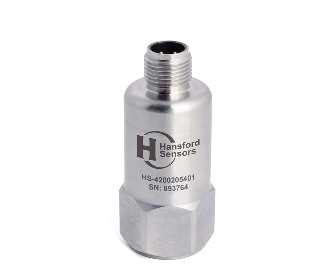
Continuous vibration velocity measurement in the PLC — trend logging and alarms.
PDF datasheet
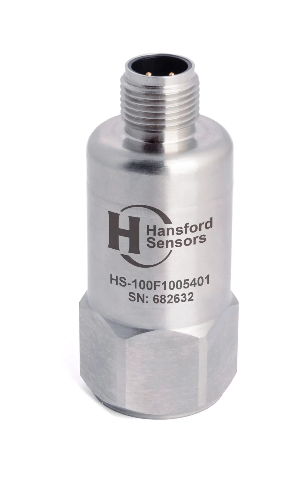
Filtered version for low-speed machines.
PDF datasheet
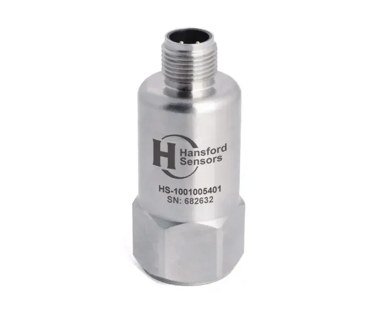
Rugged general-purpose accelerometer for periodic measurements and online monitoring systems.
At low rotational speeds, bearing fault signals are weak and low in frequency, so it is worth choosing the HS-100F — a filtered version intended for low-speed machines — or an AC accelerometer with a higher sensitivity. Mount the sensor rigidly, on a stud, as close to the bearing load zone as possible. The choice of a specific version depends on the rotational speed and the required frequency range, which you can compare in the datasheets.
The HS-420 provides the overall vibration velocity level, which is a good indicator of unbalance, misalignment and looseness. Early-stage bearing damage, however, shows up mainly at higher frequencies and in envelope analysis. Detecting it requires an AC signal from an accelerometer such as the HS-100, analysed with a data collector or in an online monitoring system. If you need both signals at one point, consider a sensor with a 4–20 mA output and an additional AC output, such as the HS-421.
Choose a braided cable or a cable in protective conduit, and route it along the structure, away from hot material and power cables. Check the permissible temperature of the selected version: according to the manufacturer, the HS-100 operates up to 150 °C, but the cable type may lower this limit. Where it is hotter, use a high-temperature version, e.g. HS-105 with an external charge amplifier.
Send us a list of machines with their rotational speeds, a description of the conditions at the mounting points and where the signal is to go. We will help you select sensors, cables and the mounting method.