
HS-558 4-channel interface module
Output: AC 100 mV/g (acceleration).
- AC IEPE
- 100 mV/g
PDF datasheet
Exclusive Hansford Sensors distributor for Poland, the Czech Republic and Slovakia
Vibration monitoring
Machine condition monitoring starts with vibration measurement, and vibration monitoring is a complete measurement chain: a sensor on the bearing housing, a cable, a connection point and a device that receives the signal — a module, a controller, an online system or a portable instrument. We describe how to build such a chain for periodic and continuous measurements and which catalogue items are used for it.
Output: AC 100 mV/g (acceleration).
PDF datasheet
PDF datasheet
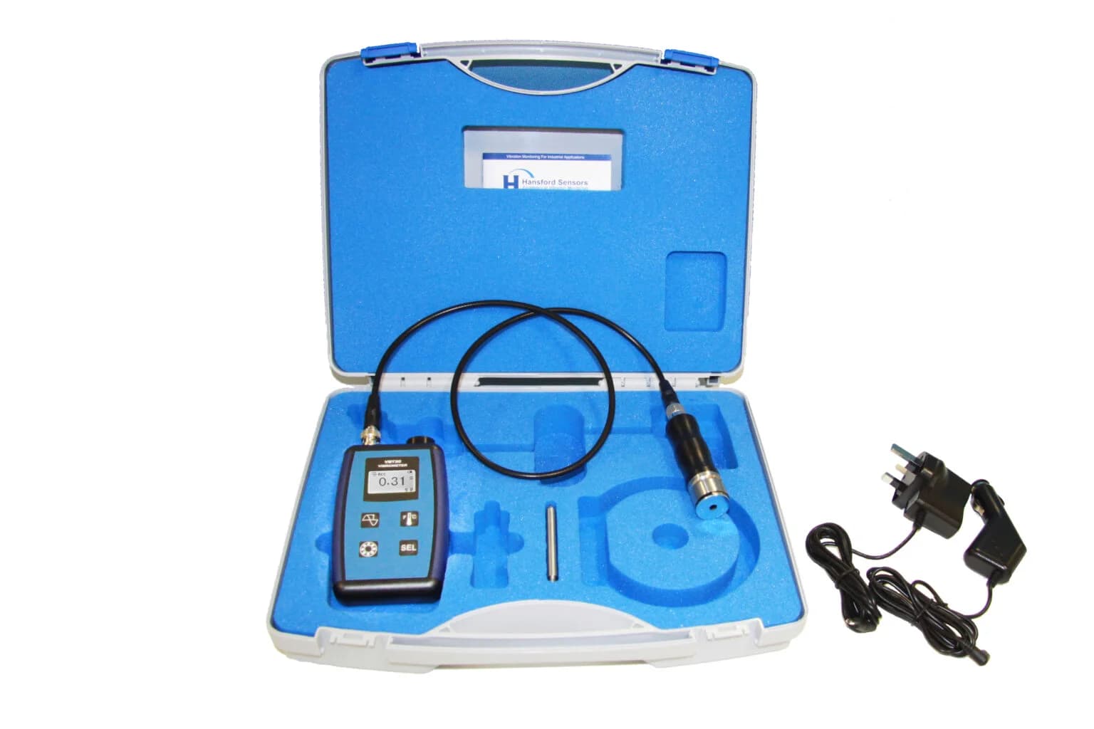
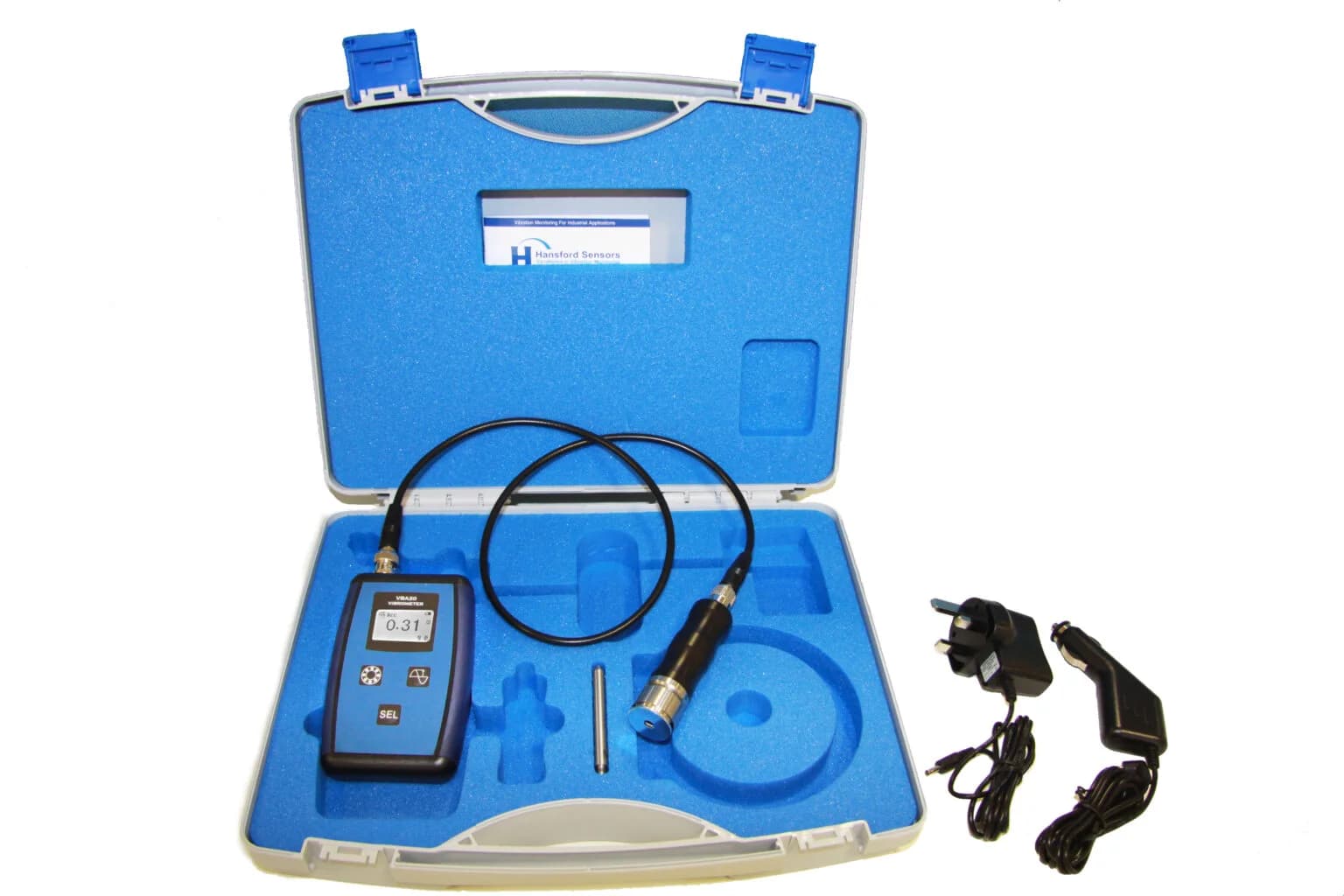
Portable meter for vibration velocity and bearing condition, for measurements without a fixed installation.
PDF datasheet
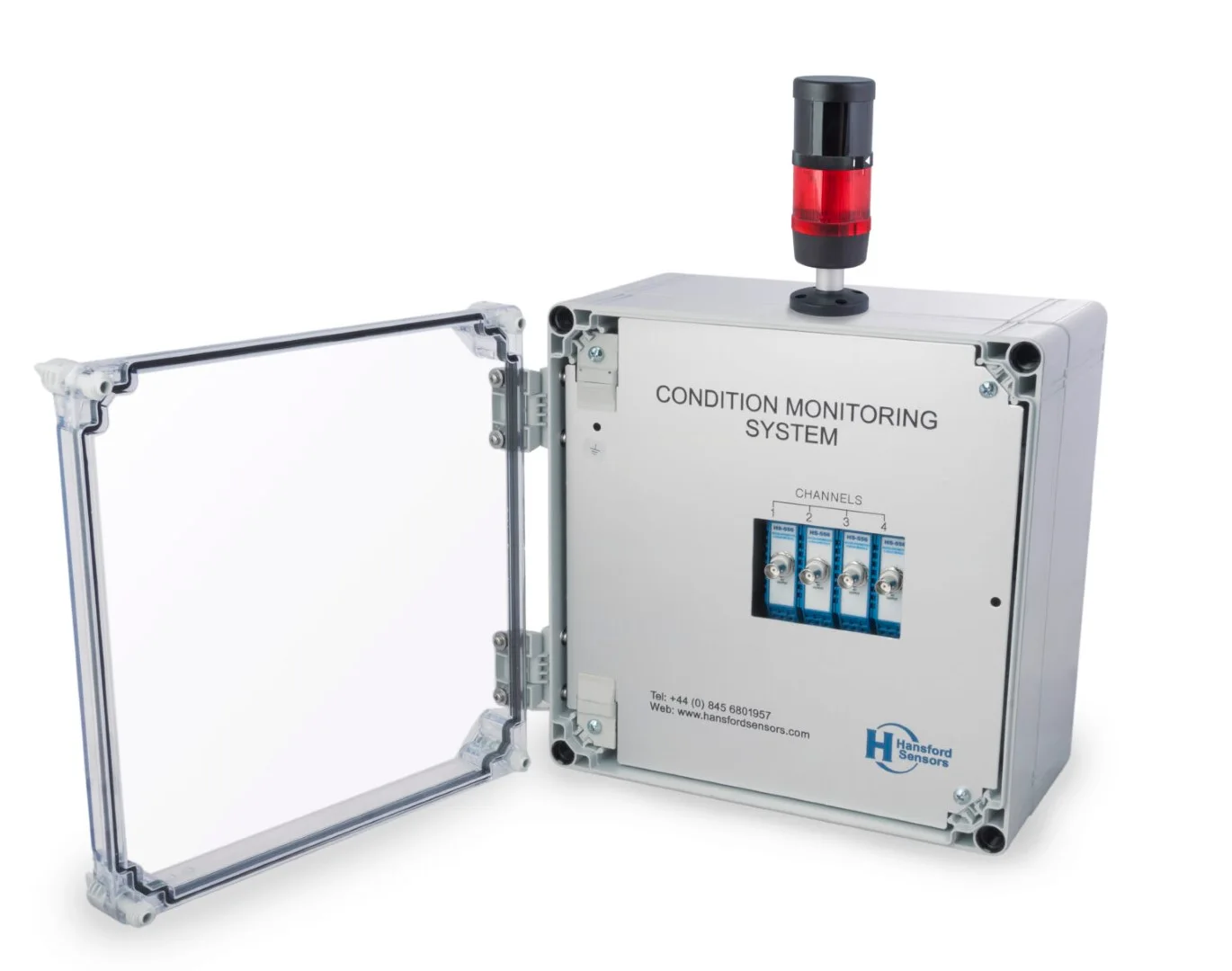
Polycarbonate enclosure.
PDF datasheet
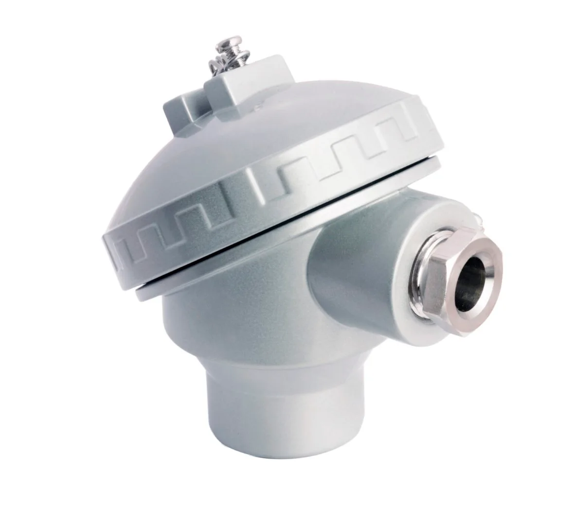
Available in aluminium or stainless steel.
PDF datasheet
Output: vibration signal.
PDF datasheet
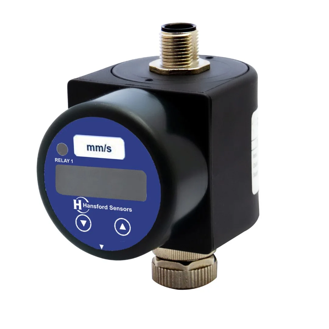
With LED display.
PDF datasheet
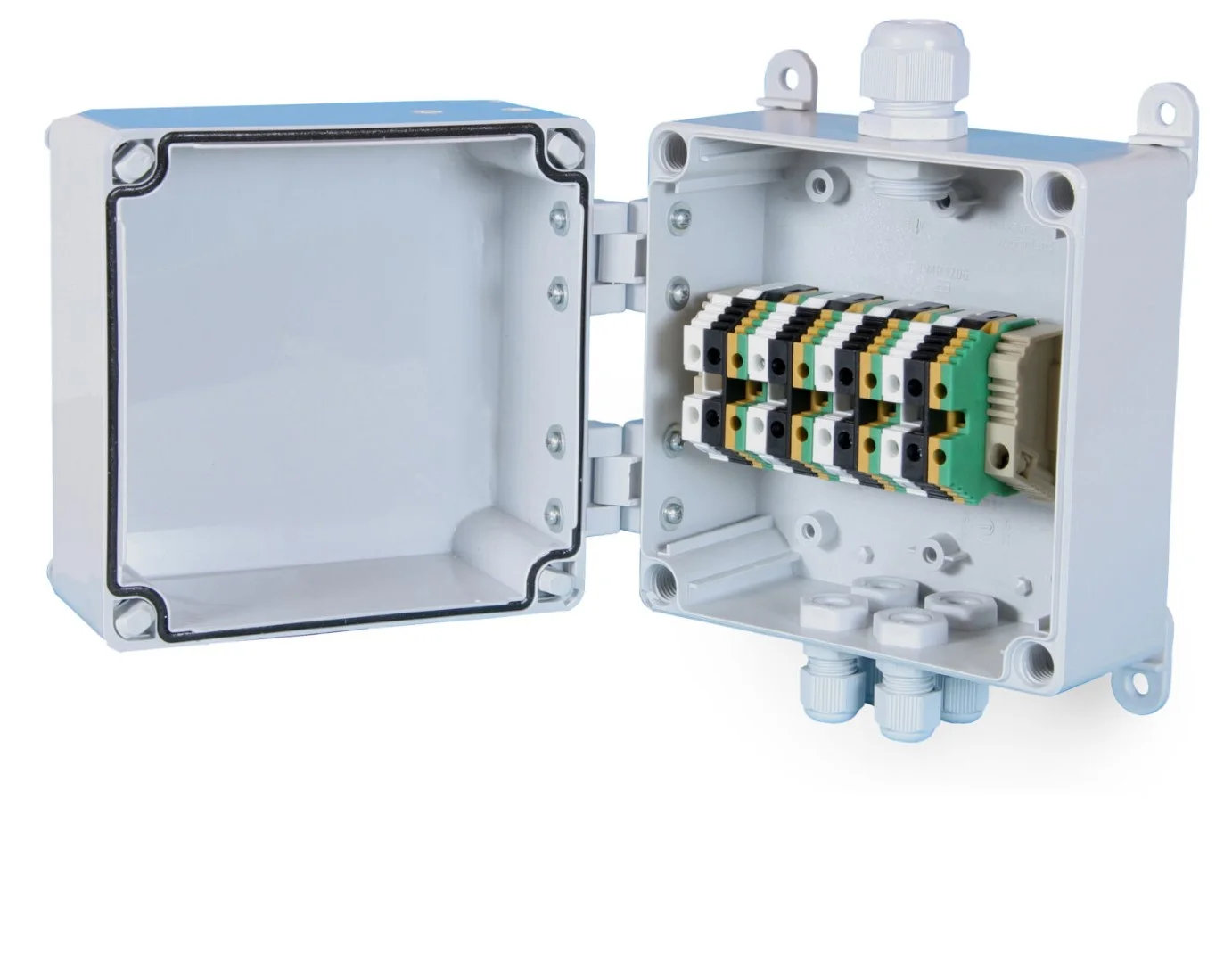
Polycarbonate enclosure.
PDF datasheet
With LED display.
PDF datasheet
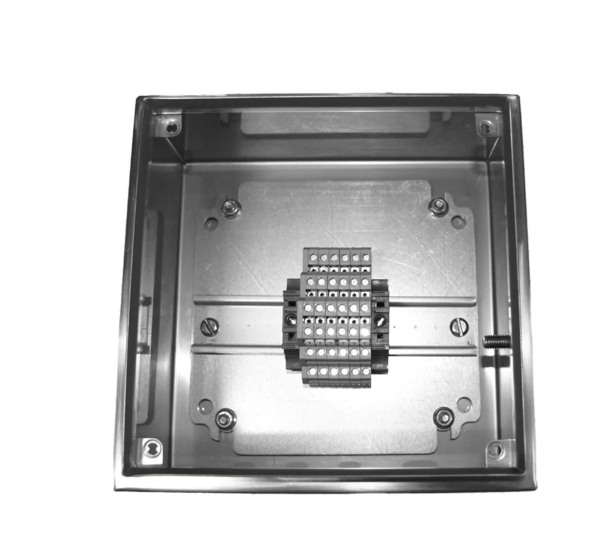
Stainless steel enclosure.
PDF datasheet
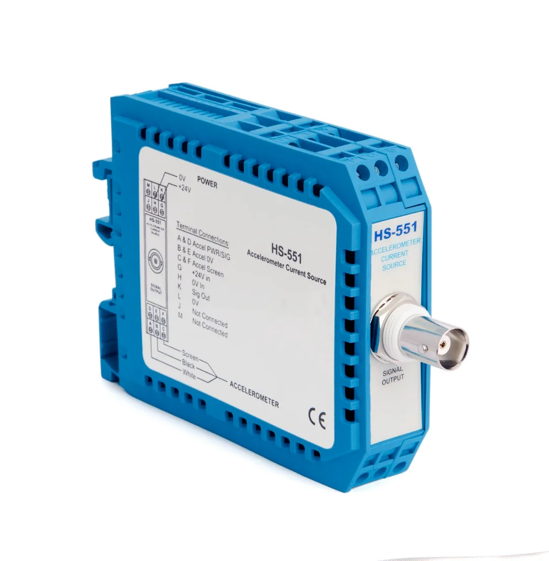
Constant-current supply for IEPE accelerometers and an AC output (mV/g) via BNC for data collection.
PDF datasheet
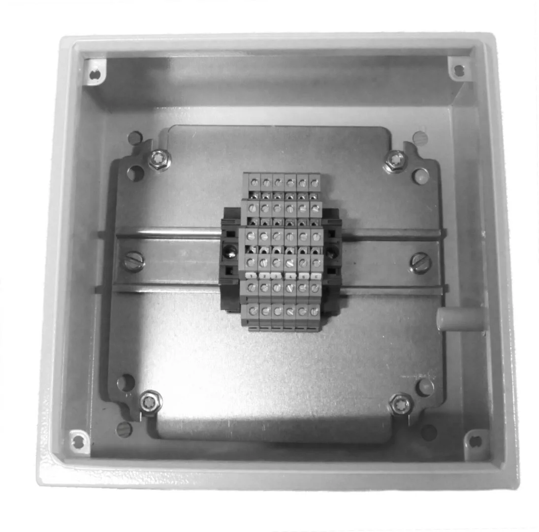
Painted mild steel enclosure.
PDF datasheet
Sensor and mounting — an AC (IEPE) accelerometer for vibration analysis or a 4–20 mA transmitter for the control system, fixed on a mounting stud, an adhesive mounting pad or a magnetic mount.
Cable — integral with the sensor or connected via a connector, with a sheath suited to the operating conditions (PUR, FR, HFFR, FEP, braided).
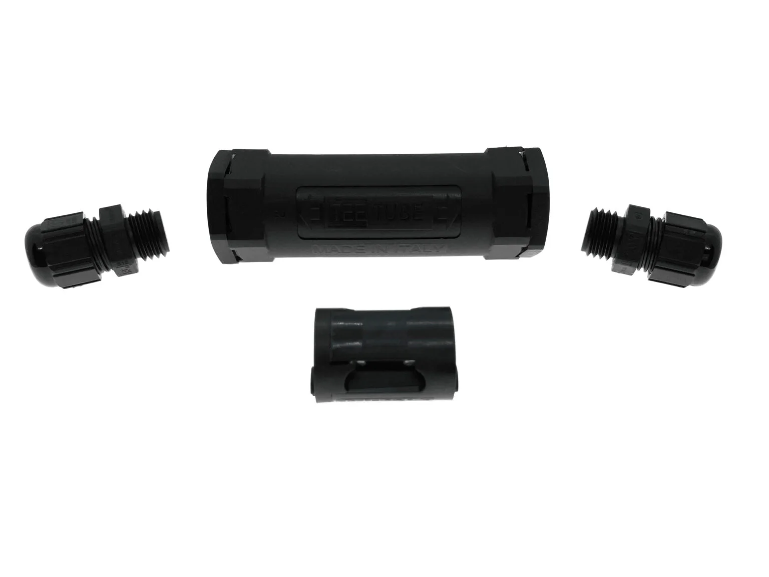
Connection point — a bracket with a BNC socket at the machine, a connection box or switch box for multiple sensors, or a junction box in which the sensor cables are joined to a multi-core cable.
Receiving the signal — a portable data collector or meter, a DIN-rail module, a PLC, a DCS or SCADA system, or an online monitoring system.
It is best to start planning from the end: the device that receives the signal determines the sensor type, and the layout of the machines and control cabinets determines the cable routes and the locations of the connection points.
In periodic measurements, a vibration analyst walks a measurement route with a portable data collector. The sensor can be attached with a magnet for each measurement, but on many machines a permanently mounted sensor, with its cable run to an accessible location, works better. The measurement is then always taken at the same point and in the same direction, without removing guards and without approaching rotating parts.
Measuring point connections — brackets with BNC sockets and connection modules for single points.
Connection boxes — a separate socket for each sensor in one enclosure.
Switch boxes — channel selection with a switch and readout of many sensors through one connector; there are also versions for triaxial sensors and versions with vibration and temperature outputs.
Data collector cables — connect the measuring point to the instrument.
For a quick condition check without a permanent installation, there are vibration meter kits — portable meters with a sensor, magnet and probe that measure vibration velocity and bearing condition.
In continuous monitoring, the sensor signal goes to the system permanently.
4–20 mA transmitters → PLC, DCS, SCADA — the overall vibration value is shown in the control system, with a trend and with warning and alarm thresholds.
IEPE accelerometers → online monitoring system — the full dynamic signal for automatic spectrum and envelope analysis.
IEPE accelerometers → DIN-rail modules — the monitoring systems category includes modules that power IEPE sensors and convert their signal to 4–20 mA or 0–10 V outputs; some of them also have a buffered AC output for data collection.
Alarm functions — vibration switches with a relay output and display units with a vibration switch function, e.g. for HS-420 and HS-422 series sensors.
Modules are powered from power supply modules and installed in module enclosures. The boxes at the machines are connected to the control cabinet with multi-core cables, and the sensor cables are joined to these in junction boxes.
Periodic and continuous measurements are not mutually exclusive. A 4–20 mA transmitter with an additional AC output sends the overall value to the controller and the dynamic signal to a socket in a connection box used by the vibration analyst. Some switch boxes have terminals prepared for later expansion with an online system, so the installation can be extended in stages.
After installation, check each measurement chain. An accelerometer tester verifies that the sensor and cable work and checks the bias voltage, and an accelerometer simulator supplies a signal of known level that can be used to check monitors and alarm circuits without running the machine. We describe the rules for correct sensor mounting in our article on mounting vibration sensors.
If you are planning a system for many machines, prepare a list of measuring points with the machine type, rotational speed, operating conditions and distance to the control cabinet — this makes it easier to select the sensors, enclosures and cables. You can send the list using the contact form or add the products straight to a quote request.
In a connection box, each sensor has its own socket, to which the data collector is connected. In a switch box, the sensors are connected to a switch, and the measurement is taken through one common connector after selecting the channel. Both solutions allow many sensors to be read from a single, safely accessible location.
Not to a typical analogue input. An IEPE accelerometer needs a constant-current supply and produces a rapidly changing AC signal that a standard controller input cannot process. You can use a module that powers the sensor and converts the signal to 4–20 mA, or choose a 4–20 mA vibration transmitter from the start.
Yes, especially if this is planned at the design stage. It helps to have permanently mounted sensors, switch boxes with terminals for expansion to an online monitoring system, dual-output sensors (4–20 mA and AC) and spare cores in multi-core cables.
An accelerometer tester lets you check the sensor, the cable and the bias voltage directly at the installation site. An accelerometer simulator supplies a signal of a known level, so you can verify the readings of modules and displays and the operation of alarms. It is worth recording the results as a baseline.
Send a list of models or describe the machine and the operating conditions — we will choose the right version and prepare a quotation.