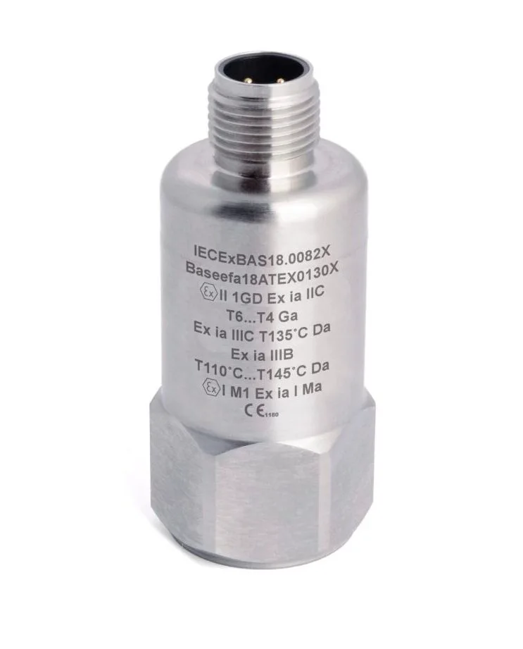
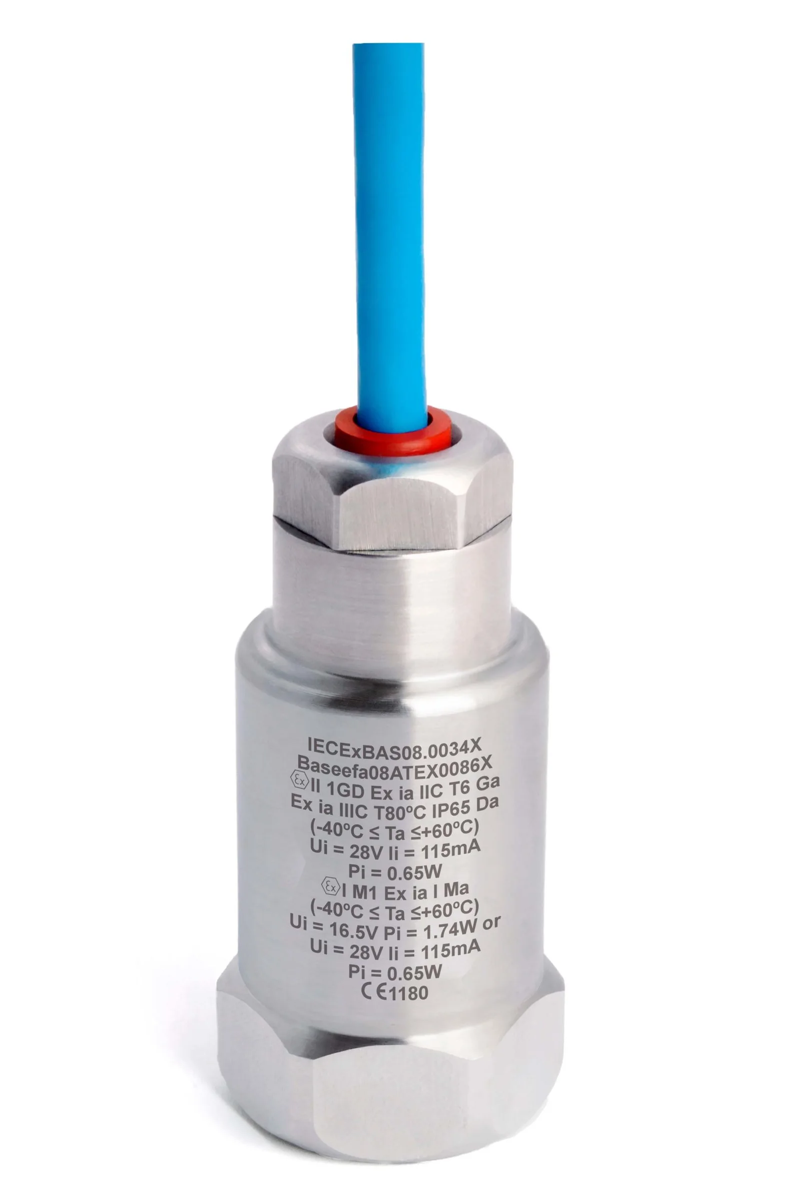
HS-100I Intrinsically safe accelerometer, top exit, M12 connector
Output: AC 100 mV/g (acceleration), M12 connector.
- AC IEPE
- 10 … 100 mV/g
- Top exit
- IP67
PDF datasheet
Exclusive Hansford Sensors distributor for Poland, the Czech Republic and Slovakia
Hazardous areas
Hazardous areas with explosive gas or dust atmospheres require vibration sensors in an explosion-protected version, with a certificate that matches the zone, group and temperature class. This page brings together intrinsically safe versions of AC accelerometers and 4–20 mA transmitters, Ex tb and Ex d versions, and accessories for measurement chains in Ex zones.
Output: AC 100 mV/g (acceleration), M12 connector.
PDF datasheet
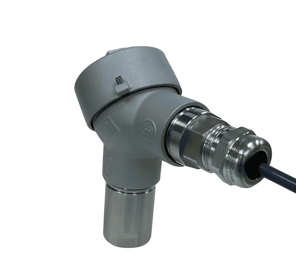
Output: 4–20 mA (vibration velocity).
PDF datasheet
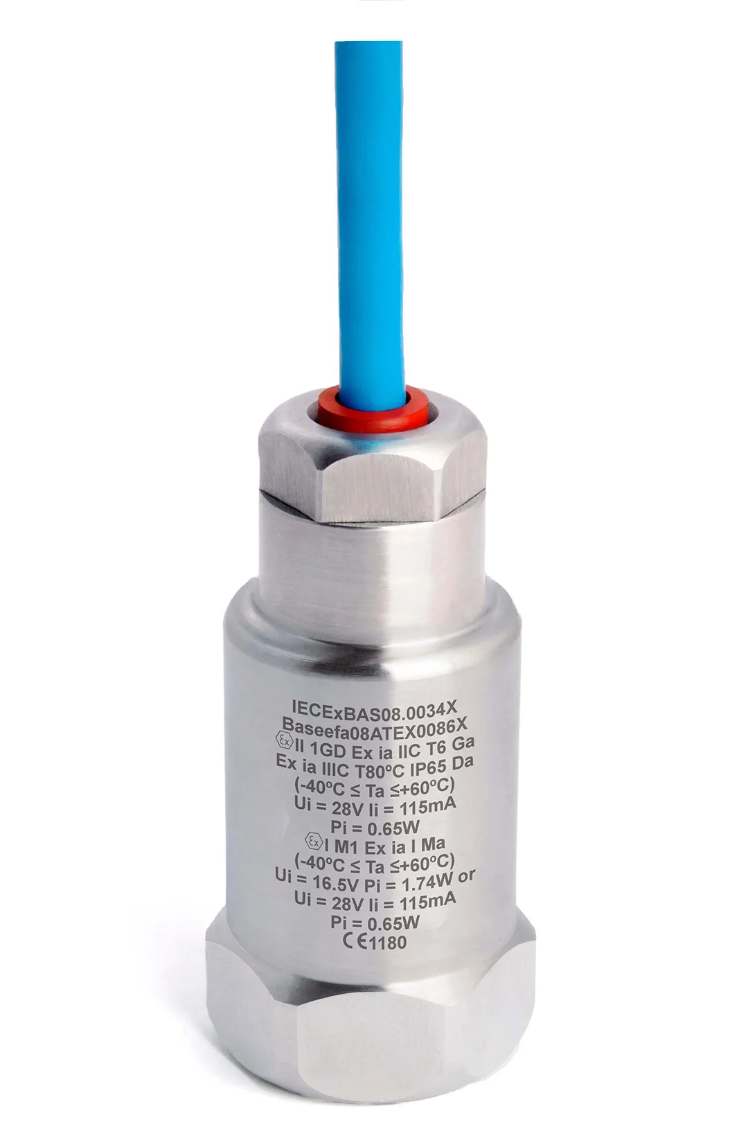
Output: 4–20 mA (acceleration), PUR cable.
PDF datasheet
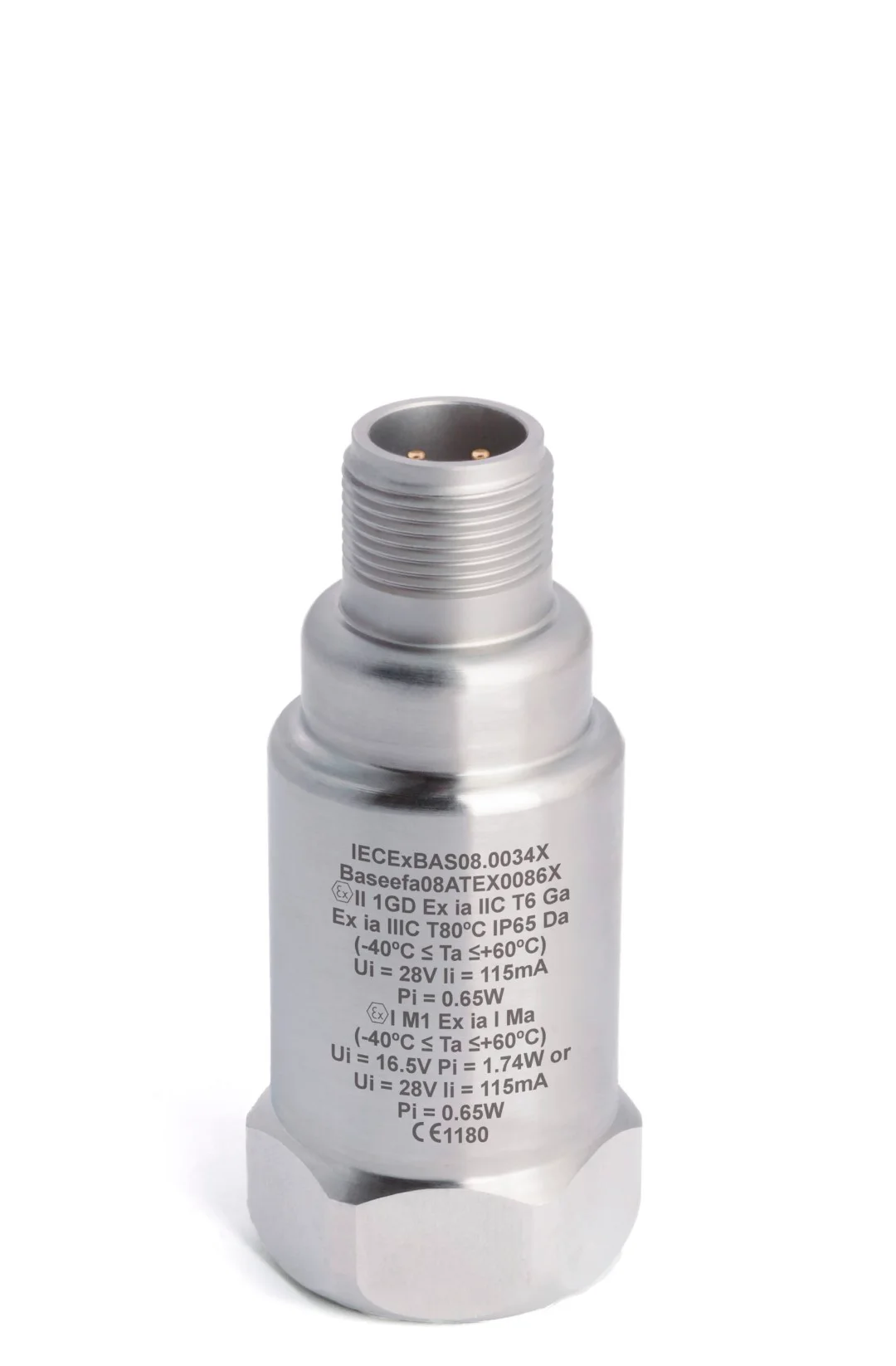
Output: 4–20 mA (acceleration), 2-pin MS connector.
PDF datasheet
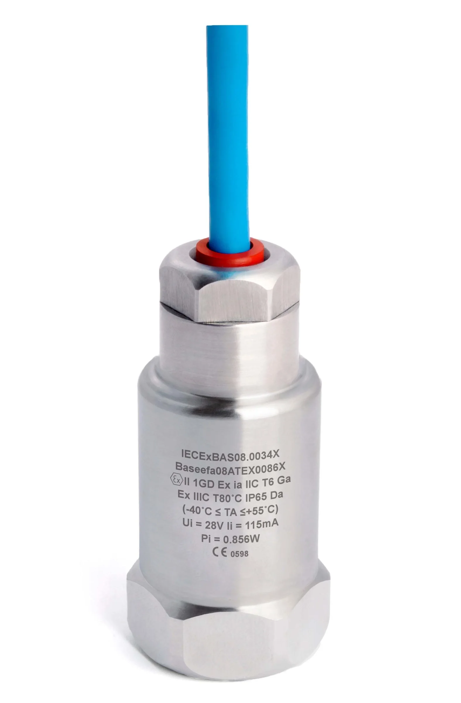
Outputs: 4–20 mA (vibration velocity) and AC (acceleration), PUR cable.
PDF datasheet
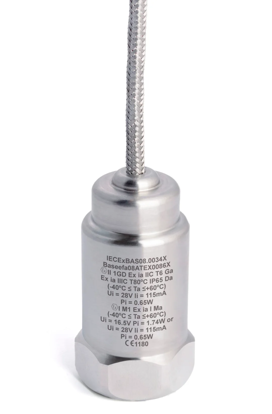
Outputs: 4–20 mA (vibration velocity) and AC (acceleration), braided cable.
PDF datasheet
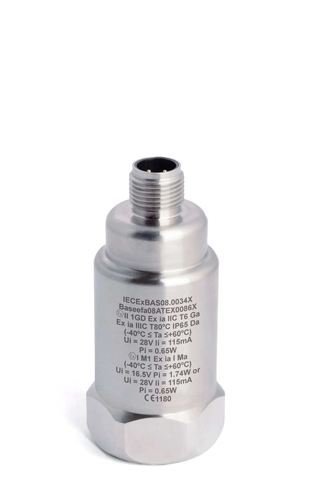
Outputs: 4–20 mA (vibration velocity) and AC (acceleration), M12 connector.
PDF datasheet
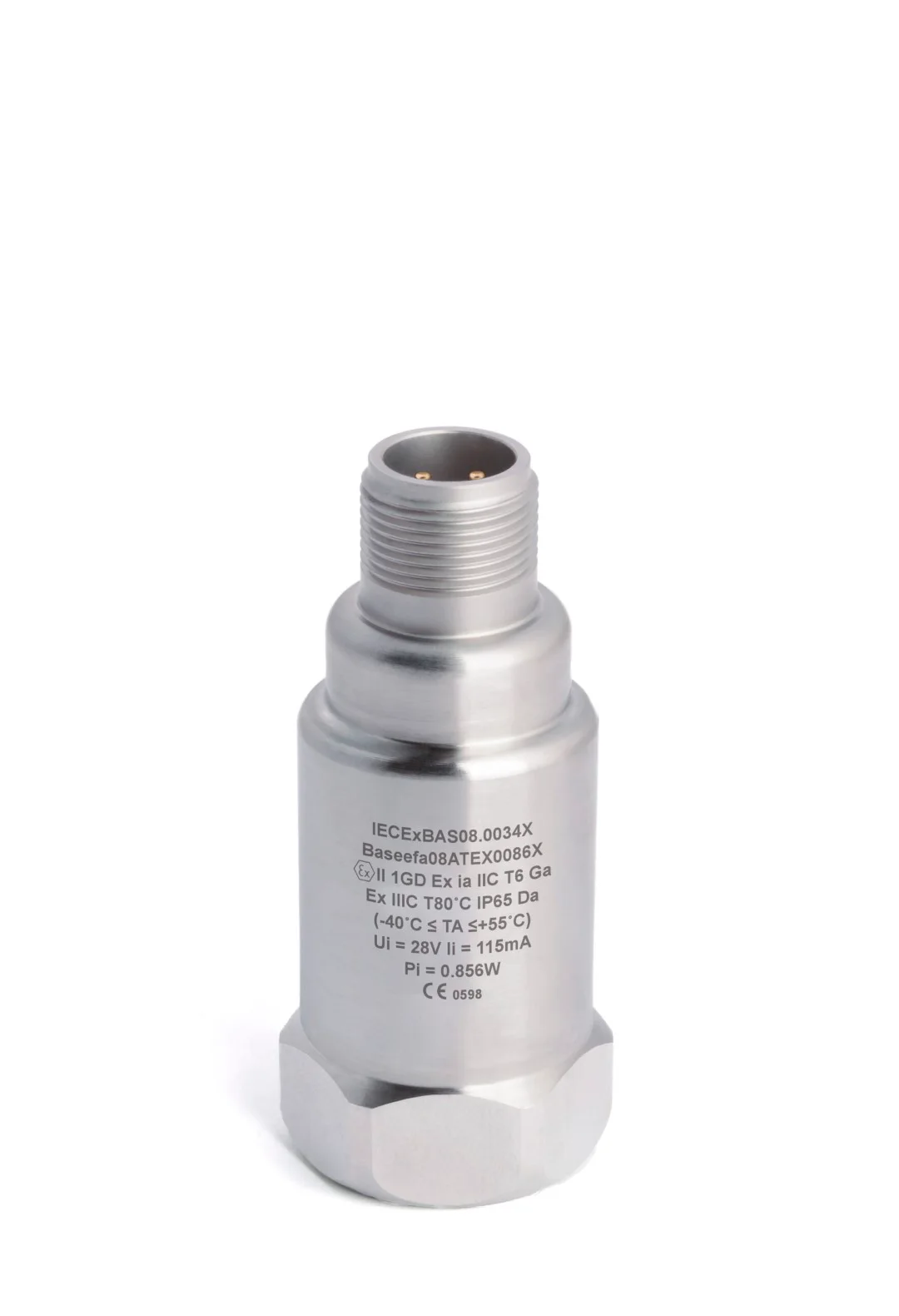
Outputs: 4–20 mA (vibration velocity) and AC (acceleration), 3-pin MS connector.
PDF datasheet
Outputs: 4–20 mA (vibration velocity) and 10 mV/°C (temperature), PUR cable.
PDF datasheet
Output: 4–20 mA (vibration velocity), PUR cable.
PDF datasheet
Output: 4–20 mA (vibration velocity), braided cable.
PDF datasheet
Output: 4–20 mA (vibration velocity), M12 connector.
PDF datasheet
Intrinsically safe accelerometers (Ex i) — AC accelerometer versions (100 mV/g as standard), including HS-100I, HS-150I and HS-170I, side-exit versions (e.g. HS-100IS), and triaxial (HS-173I), high-temperature (HS-105I) and low-power (HS-104I) versions. Category: accelerometers for Ex zones.
Intrinsically safe 4–20 mA transmitters — vibration velocity (HS-420I/M), acceleration (HS-422I/M), versions with an additional AC output (HS-421I) and with a temperature output (HS-420IT, HS-422IT). Category: intrinsically safe 4–20 mA transmitters.
Ex tb — an accelerometer with protection by enclosure, designed for dust zones (HS-150tb).
Ex d — a 4–20 mA transmitter with a flameproof connection head (HS-420d).
Accessories — intrinsically safe connection boxes and an intrinsically safe display unit with a vibration switch function (HS-517I) for HS-420I and HS-422I series sensors.
The manufacturer offers intrinsically safe versions with ATEX certification, and some of them also with IECEx certification. The scope of approval of a specific model — Ex marking, ambient temperature range and circuit parameters — is given in its specification and certificate.
In the model designation, an intrinsically safe version is identified by the letter “I” (e.g. HS-100I), or by “IS” in side-exit versions (e.g. HS-150IS). In the product specifications, check the “Hazardous-area version” and “Approvals and certificates” entries, and in the “Documentation” section, the datasheet with the explosion protection marking.
Establish the zone (0, 1, 2 for gases; 20, 21, 22 for dusts) on the basis of the plant documentation.
Determine the required equipment category or equipment protection level (EPL), the gas or dust group and the temperature class.
Check the ambient temperature at the mounting point — including heat from the machine — and compare it with the Ta range in the sensor marking.
Choose the signal type: AC (IEPE) for vibration analysis or 4–20 mA for the control system.
Select a Zener barrier or galvanic isolator with parameters that match the sensor certificate — with a separate channel for each measurement chain.
Check the cable parameters and length, as well as the requirements for cable glands and connections.
Gather the documentation: certificates, declarations of conformity, datasheets and manuals.
Signal selection in an Ex zone follows the same rules as outside it: intrinsically safe 4–20 mA transmitters send the overall vibration value to the DCS or PLC, while intrinsically safe AC accelerometers send the full signal for analysis. If you need both, the HS-421I combines a 4–20 mA output with an AC signal in one sensor; how both signals are connected through barriers is specified in the certificate and the manufacturer’s instructions.
We explain zones, categories, intrinsic safety and the matching of circuit parameters in the guide Vibration sensors in hazardous areas.
An intrinsically safe sensor operates in a circuit with associated apparatus — a Zener barrier or a galvanic isolator — located outside the hazardous area or in a suitable enclosure. The barrier’s output parameters must be compatible with the sensor’s input parameters, and the capacitance and inductance of the cable limit its permissible length. The barrier must also suit the signal type — powering an IEPE accelerometer has different requirements from a 4–20 mA loop.
The manufacturer provides guides on safety barriers and on the maximum cable length for intrinsically safe versions. You will find them with the products, in the “Documentation” section, and in the document library.
The “Documentation” section of each product page contains datasheets (in metric and imperial units) and, for Ex versions, usually also manuals, system diagrams and the manufacturer’s guides. Certificates and other manufacturer documents are collected in the document library. Most documents are in English. If you need a document for a specific model that is not available with the product, write to us using the contact form.
Both are acceptable if their parameters are compatible with the sensor’s certificate and suit the signal type. A Zener barrier is simpler but requires a reliable intrinsically safe earth. A galvanic isolator separates the circuits galvanically, does not need such an earth and reduces problems with earth loops. The choice rests with the installation designer.
Yes, if its certificate covers both types of atmosphere. The marking then has separate lines for gases and for dusts. Each line may have a different ambient temperature range and a different temperature class or surface temperature, so check the line that applies to the conditions at the mounting location.
The letter “X” at the end of a certificate number means that the equipment has special conditions for safe use. They are described in the certificate and the instructions and must be taken into account in the design and during installation. They may concern, for example, the connection method, protection against electrostatic charges or the temperature range.
Only if the collector itself and the accessories used with it are approved for use in that zone. Another option is to bring the sensor signals out to a reading point outside the hazardous area, in accordance with the intrinsically safe installation design.
Send a list of models or describe the machine and the operating conditions — we will choose the right version and prepare a quotation.