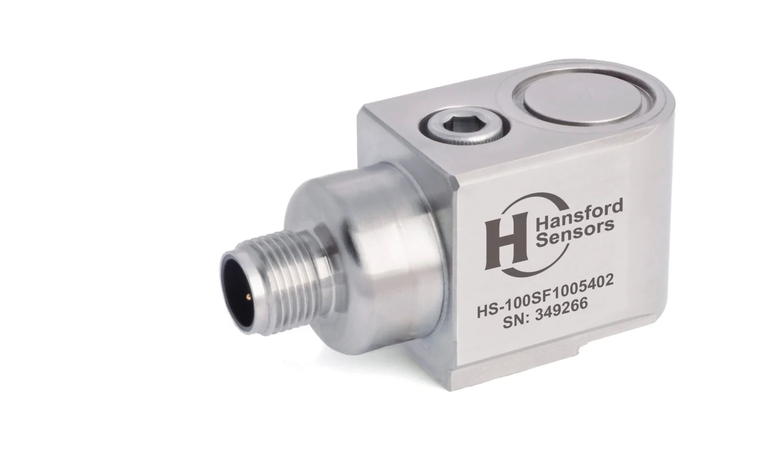
HS-100SF Accelerometer with filter, side exit, M12 connector
- AC IEPE
- 10 … 500 mV/g
- Side exit
- IP67
PDF datasheet
Exclusive Hansford Sensors distributor for Poland, the Czech Republic and Slovakia
In a wind turbine, a serious failure usually means a crane, waiting for a weather window and lost energy production. Accelerometers on the main bearing, gearbox and generator make it possible to track how damage develops and to plan service work before a minor fault turns into a component replacement.

Access to the nacelle is limited: work is carried out at height and depends on the weather and, on offshore wind farms, also on sea conditions. Replacing a main bearing, gearbox or generator requires a heavy crane and long planning. A gearbox bearing fault detected at an early stage can be monitored and the repair planned for a convenient time; if detected too late, it can destroy the gear teeth and lead to replacement of the entire gearbox.
The main shaft rotates slowly and the gearbox increases the speed in several stages, so in one turbine both very low and high frequencies must be measured. Rotational speed and load change with the wind, so results are compared under similar operating conditions.
Sensors operate under large temperature variations, in humidity and condensation, and offshore also in salt mist, while signal cables run close to power cables and the converter. This requires sealed housings, screened cables and careful cable routing.
01Machines in this industry
Main bearing, main gearbox (planetary and parallel stages), generator and others — measuring point on the bearing housing.
02Sensor
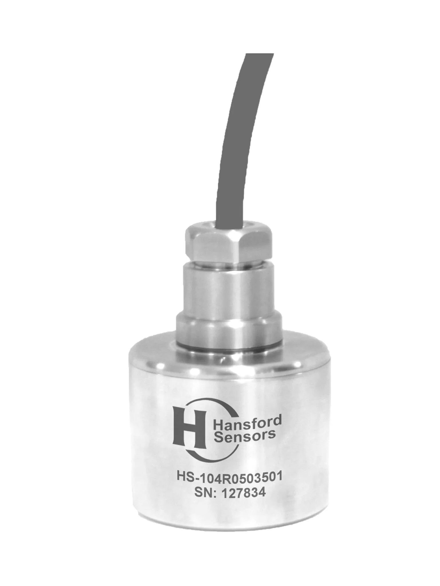
An IEPE accelerometer or a 4–20 mA sensor converts vibration (and often temperature) into an electrical signal.
Industrial IEPE accelerometers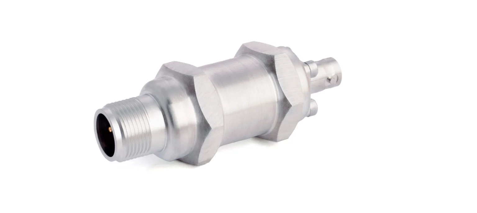
03Signal
A cable with the right connector and a junction box carry the signal from many measuring points to the system.
Cables and connectors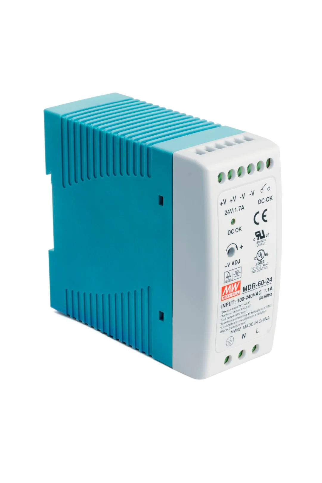
04Monitoring
PLC, DCS, an online system or a data collector: trends, alarm thresholds and diagnostics before a failure happens.
Vibration systems and switchesThe HS-100SF series is intended for measuring slow movements — side exit accelerometers with a filter and a response improved at low frequencies. The manufacturer offers them in various sensitivities, including ones above the standard 100 mV/g, which helps at very low speeds. The standard frequency range of AC accelerometers is 0.8 Hz – 15 kHz (±3 dB) and can be adjusted with filters; exact data for each version are given in the datasheet.
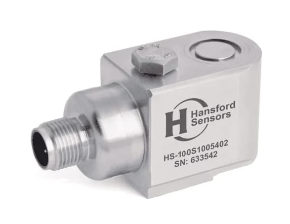
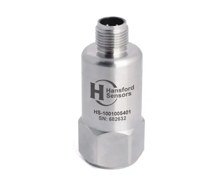
On the faster gearbox stages and on the generator, the general-purpose HS-100 accelerometer works well. It is available with a braided cable or a connector, among other options. Where space in the nacelle is limited, the side exit version HS-100S can be used, with an M12 connector and a separate cable assembly. When three measurement directions are needed at one point, a triaxial accelerometer replaces three separate sensors and simplifies the wiring.
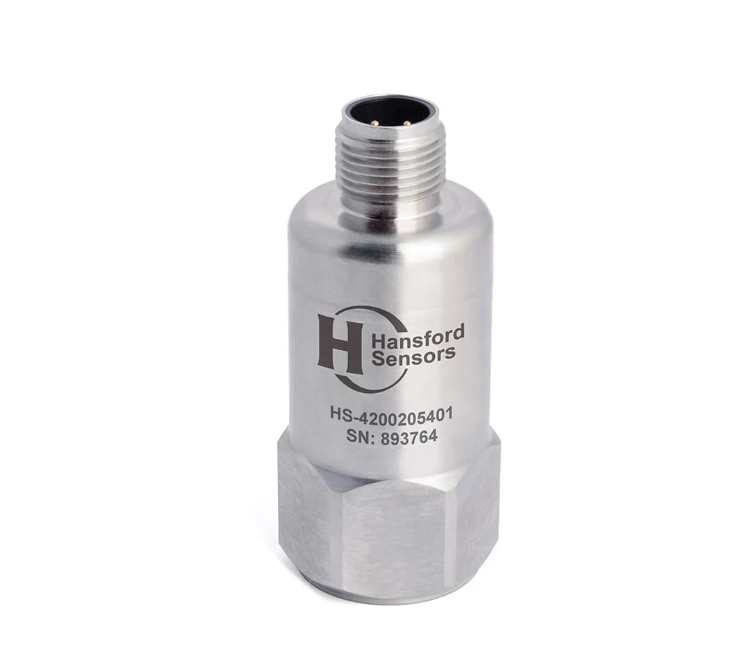
HS-420 sends a 4–20 mA signal proportional to vibration velocity directly to the turbine controller or the wind farm SCADA system. This is a good solution for continuous monitoring and alarms where spectrum analysis is not needed.
In new designs, the sensor is usually mounted on a stud screwed into a tapped hole in a spot-faced surface of the housing. In retrofits, where drilling the gearbox or bearing housing is impractical, adhesive mounting pads are used — see sensor mounting hardware.
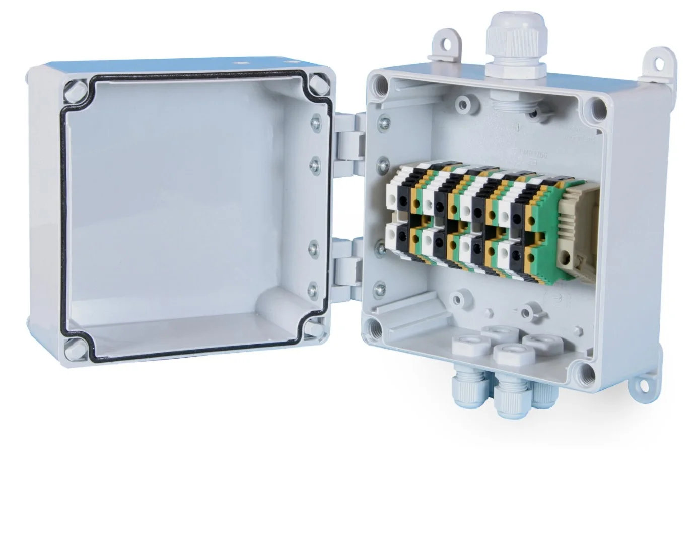
Sensor cables are brought together in an HS-JE junction box in the nacelle, from where a multi-core cable runs down the tower to the monitoring system or to a switch box at the base.
PDF datasheet
Filtered version for low-frequency measurements (low-speed main bearings).
PDF datasheet
Side exit — for mounting in a cramped nacelle.
PDF datasheet
Junction box for local cable connections.
PDF datasheet
4–20 mA signal for turbine control systems and SCADA.
PDF datasheet
General-purpose accelerometer for the gearbox and generator.
The main shaft rotates very slowly, so the characteristic bearing defect frequencies are low and the signal is weak. This requires a sensor with a good low-frequency response and often a higher sensitivity, e.g. HS-100SF. The generator runs at a much higher speed, so a general-purpose accelerometer such as the HS-100 is usually sufficient.
The vibration level depends on the turbine’s rotational speed and load, so results are only compared under similar operating conditions. The monitoring system should record the rotational speed and power together with each measurement, and keep separate trends for several operating ranges. This makes it possible to tell a developing fault from an ordinary change in conditions.
Yes. In retrofits, adhesive mounting pads are often used, and the sensor is screwed onto the pad. The surface must be cleaned and prepared, and the pad bonded with an adhesive intended for mounting vibration sensors. A well-made bond transmits vibration over a wide frequency range. Where it is possible, stud mounting in a tapped hole remains the preferred method.
Tell us the turbine type, the measurement points and the monitoring system requirements: sensitivity, power supply, connectors. We will help you select sensors, mounting hardware and junction boxes.