GuideSensor selection6 min read
How to choose a vibration sensor for your machine
Choosing a vibration sensor starts with the question of where the signal will go. Step by step, we cover the output type, measured quantity, sensitivity, frequency range, operating conditions, connection type, mounting and number of axes — with a checklist at the end.
Author: HS SensorsPublished
The vibration sensor is the first link in the measurement chain, and its specifications limit everything downstream. A poorly chosen accelerometer may miss a developing bearing fault, saturate at high vibration levels or fail prematurely in a harsh environment. Below, we set out a sequence of decisions that works well in maintenance practice — from the purpose of the measurement to the ordering details.
1. What will the signal be used for?
This is the most important question, because the answer determines the sensor’s output type.
Vibration analysis, data collector, online monitoring system — you need a dynamic vibration signal from which the spectrum, envelope and time waveform can be derived. This signal is provided by an industrial AC (IEPE) accelerometer, whose output is an AC voltage proportional to acceleration.
Trending and alarms in a PLC, DCS or SCADA system — a single overall vibration value transmitted as a 4–20 mA signal is enough. In that case, the right choice is a loop-powered 4–20 mA vibration transmitter, connected directly to a PLC analogue input.
Both — a dual-output sensor, for example one with a 4–20 mA output proportional to vibration velocity and a parallel AC acceleration signal, lets you raise alarms in the PLC while also carrying out periodic analysis with a data collector at the same point.
We explain the differences between the two signal types in our article comparing IEPE accelerometers and 4–20 mA transmitters.
2. Measured quantity
An accelerometer measures acceleration; an instrument or module can convert this to vibration velocity by integration. RMS velocity in mm/s is a widely used measure of overall machine condition, whereas acceleration better reveals high-frequency phenomena such as early-stage rolling-element bearing damage or gear meshing. Accordingly, 4–20 mA transmitters are ordered in a version proportional either to velocity or to acceleration. For instruments and systems that expect a velocity signal, use velocity-output sensors.
If you also want to monitor the bearing housing temperature at the same point, choose a version with an additional temperature output — 10 mV/°C or PT100. One sensor means one mounting point and one cable.
3. Sensitivity or measuring range
The standard sensitivity for AC accelerometers in vibration diagnostics is 100 mV/g, which suits most rotating machines: motors, pumps, fans and gearboxes. A lower sensitivity (e.g. 10, 30 or 50 mV/g) is chosen for high vibration and shock levels, where the signal at 100 mV/g could exceed the output range of the sensor or the input range of the instrument. A higher sensitivity (e.g. 250 or 500 mV/g) is used for very low vibration levels, typical of low-speed machines, where the useful signal approaches the noise floor of the measurement chain. Available sensitivities depend on the model.
For 4–20 mA transmitters, you select a measuring range instead of a sensitivity, e.g. 0–25 mm/s or 0–2 g. The range should cover the expected vibration levels with headroom for alarm conditions. However, it must not be too wide, or typical values will occupy only a small part of the signal span.
4. Matching the frequency range to running speed and fault type
The manufacturer’s standard frequency range for AC accelerometers is 0.8 Hz – 15 kHz (±3 dB), and it can be adapted to the application with a filter if required; the frequency range of a specific model is given in its datasheet. To check whether it is sufficient, convert the running speed to frequency: a shaft rotating at 1500 rpm corresponds to 25 Hz.
Unbalance, misalignment, looseness — components at the rotational frequency and its low multiples.
Rolling-element bearings — characteristic defect frequencies and high-frequency components excited by impacts, analysed using envelope demodulation.
Gearboxes — gear mesh frequency (number of teeth multiplied by the shaft rotational frequency) with its harmonics and sidebands.
Low-speed machines need a sensor with good low-frequency response, while bearing and gearbox diagnostics need a wide range that extends to high frequencies. The mounting method also limits the upper end of the usable range: a stud transmits high frequencies better than a magnetic mount.
5. Operating conditions
Temperature — compare the sensor’s operating temperature range with the temperature at the mounting point, and the cable’s temperature range with the conditions along its entire route, e.g. near furnaces, dryers or rolling mills. Within the same model, the range can depend on the version: a PUR cable has a narrower range than a braided or FEP cable. For temperatures beyond the capability of standard sensors, use high-temperature accelerometers with an external charge amplifier — the HS-105, for example, operates at up to 250 °C.
Water and washdown — in the food and pharmaceutical industries, machines are washed down regularly, often under pressure and with chemical agents. Match the IP rating to the washdown method and the risk of flooding; the sealing of the sensor-to-cable connection also matters.
Oils, chemicals, abrasion — these mainly determine the choice of cable sheath.
Explosive atmospheres — in Ex zones you need a version with the appropriate certification, e.g. an intrinsically safe accelerometer or an intrinsically safe 4–20 mA transmitter, as well as a correctly designed circuit with a safety barrier. For details, see our guide on vibration sensors in hazardous areas.
6. Connector or integral cable
A sensor with a connector (e.g. M12, or a 2-pin or 3-pin MS connector) can be disconnected and replaced without dismantling the whole installation, and the cable is selected separately from our range of cables and connectors. An integral cable is connected to the sensor at the factory, so there is no additional joint that could work loose or let in moisture — this matters where there is washdown, flooding or severe vibration. However, replacing the sensor means replacing the cable as far as the nearest connection point.
For integral-cable versions, you choose the sheath type:
PUR — resistant to oils and abrasion; a general-purpose choice in industrial plants.
Braided — additional mechanical protection against cutting and crushing.
FR — flame-retardant cable.
HFFR — halogen-free, for locations where smoke and halogen gas emissions must be limited in the event of fire.
FEP — for high temperatures and chemical environments.
On sections particularly exposed to damage, a cable in protective conduit can be used. The cable length is specified when ordering.
7. Top exit or side exit
A top exit brings the cable out along the sensor axis and is the most common choice. A side exit gives a low profile — useful in tight spaces, under guards and wherever a protruding cable would be exposed to impact or dust build-up. Measure the free space above the measurement point, allowing for the cable bend radius and room for the connector.
8. Mounting and thread
Stud mounting on a prepared, flat seat provides the stiffest connection and the widest usable frequency range. Where drilling is not possible, an adhesive mounting pad is used, and for periodic measurements, a magnetic mount. When ordering, specify the mounting thread, e.g. 1/4"-28 UNF, M6, M8, M10 or Quick Fit (availability depends on the model). The advantages and limitations of each method are discussed in our article on mounting vibration sensors, and you will find the accessories in the sensor mounting hardware category.
9. Number of axes
A typical measurement point uses a single-axis sensor mounted radially. Where measurements are needed in several directions at one location — horizontal, vertical and axial — a biaxial or triaxial sensor replaces several single-axis sensors, simplifies installation and reduces the number of cables. Triaxial versions are available with both AC and 4–20 mA outputs. Specifications can differ between axes, so check them in the datasheet.
Checklist
Where will the signal go: a data collector or analyser, an online monitoring system, or a PLC/DCS/SCADA system?
What are you measuring: acceleration, velocity, or perhaps temperature as well?
Which sensitivity (100 mV/g as standard) or which 4–20 mA range?
What is the machine’s running speed, and which faults do you want to detect?
What is the temperature at the mounting point and along the cable route?
Is there water, washdown, oil or chemicals — which IP rating and which cable sheath?
Is the measurement point in a hazardous area — and if so, which zone?
Connector or integral cable, and what length?
Top exit or side exit — how much space is there above the measurement point?
Which mounting method and which thread?
How many axes, and how many measurement points on the machine?
Add the selected models to your quote request and specify the required options there. If your application is non-standard, describe the machine and operating conditions in the contact form — we will help you select a sensor.
Products in this article
Full catalogue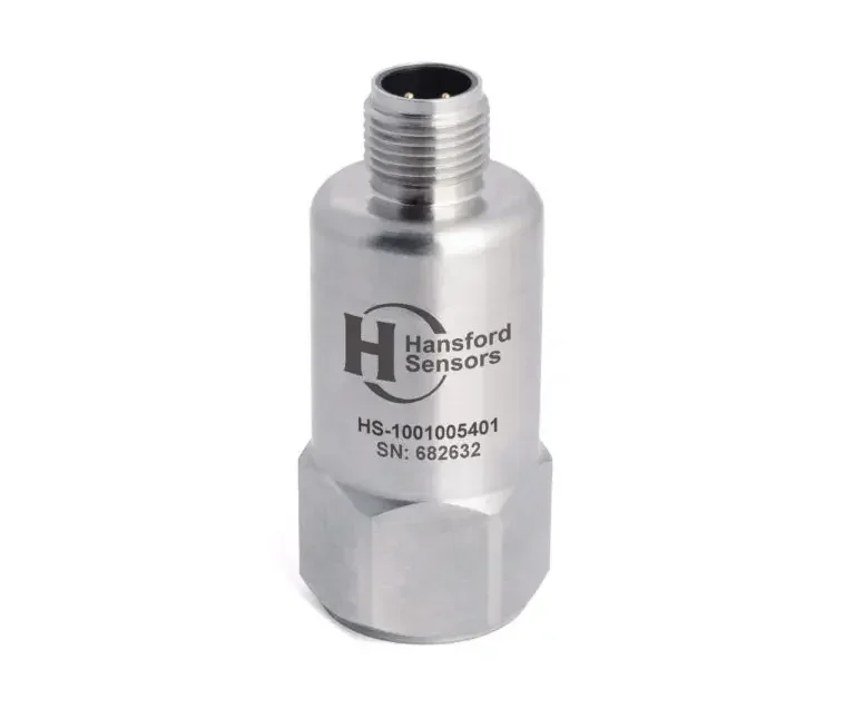
HS-100 Industrial AC accelerometer, top exit, M12 connector
- AC IEPE
- 10 … 500 mV/g
- Top exit
- IP67
PDF datasheet
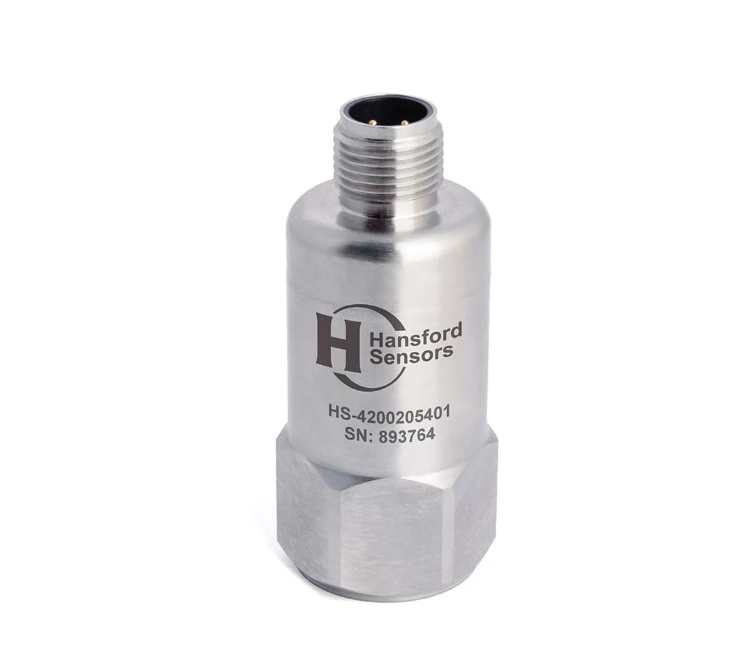
HS-420 4–20 mA vibration sensor (velocity), top exit, M12 connector
- 4–20 mA
- Top exit
- IP68
- M12
PDF datasheet
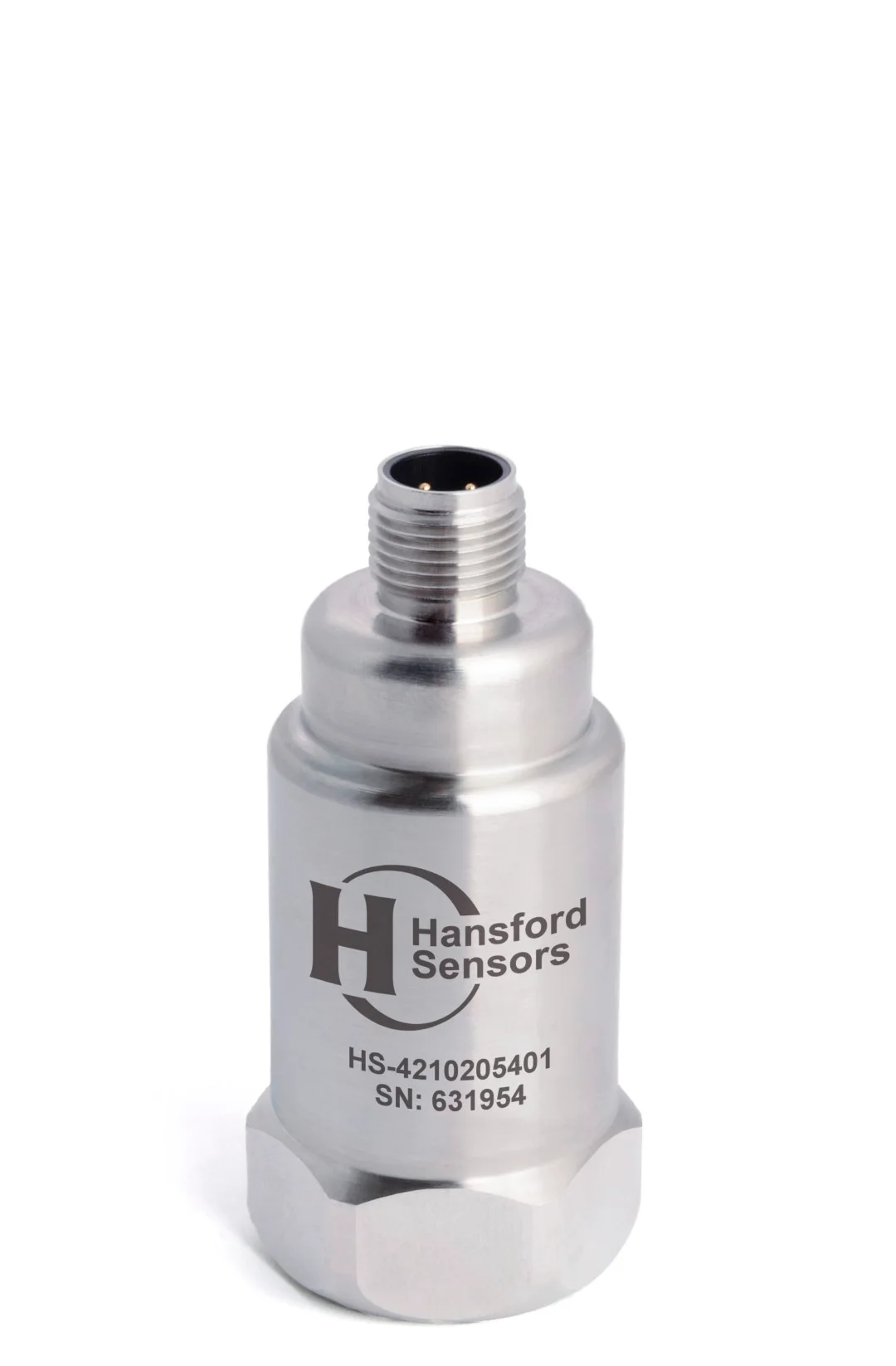
HS-421 4–20 mA vibration sensor (velocity) with additional AC output, top exit, M12 connector
- AC IEPE + 4–20 mA
- Top exit
- IP67
- M12
PDF datasheet
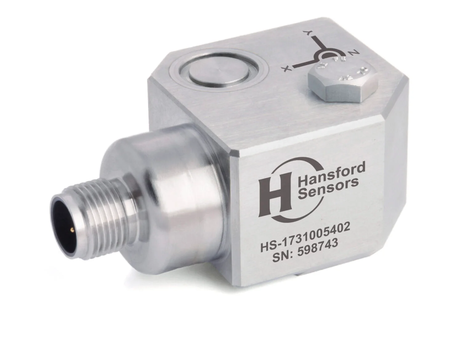
HS-173 Triaxial accelerometer, side exit, M12 connector
- AC IEPE
- 10 … 500 mV/g
- Side exit
- IP67
PDF datasheet
Related reading
Guide · Sensor selection · 5 min read
IEPE accelerometer or 4–20 mA transmitter? A comparison
An IEPE accelerometer delivers the full vibration signal for analysis, while a 4–20 mA transmitter delivers a single overall value to the PLC. We explain how both types work, how they differ and when a dual-output sensor is worth using.
Guide · Mounting and installation · 5 min read
Mounting a vibration sensor: stud, adhesive or magnet?
The mounting method determines which frequencies the sensor can measure and whether successive measurements will be comparable. We compare studs, adhesive mounting pads and magnetic mounts, and cover surface preparation, measurement direction, cable routing and common mistakes.
Guide · Hazardous areas · 6 min read
Vibration sensors in Ex zones: a selection and installation guide
In a hazardous area, a vibration sensor is part of the explosion protection system, not just a measuring instrument. We explain zone classification, the principle of intrinsic safety, the role of barriers and what to check in the certificate and documentation.