ArticleVibration diagnostics5 min read
Vibration velocity or acceleration — what should you measure?
Displacement, velocity and acceleration describe the same motion, but each of them emphasises a different frequency range. We explain when to measure velocity in mm/s RMS, when acceleration in g and the envelope, and when displacement.
Author: HS SensorsPublished Updated
The vibration of a point on a bearing housing can be described in terms of displacement, velocity or acceleration. These three quantities are physically related, but each of them emphasises a different frequency range — so the quantity you choose determines which faults will show up clearly in the results and which will be lost in the background.
One motion, three descriptions
For sinusoidal vibration at frequency f, velocity equals displacement multiplied by 2πf, and acceleration equals velocity multiplied by 2πf. This leads to some simple rules:
displacement emphasises low-frequency components,
velocity gives a more even picture across the frequency range typical of most mechanical faults,
acceleration emphasises high-frequency components.
Example: two components with the same vibration velocity, one at 25 Hz and the other at 2500 Hz, differ in acceleration by a factor of 100. In a displacement spectrum, the second would be practically invisible, whereas in an acceleration spectrum it would dominate.
Velocity — a measure of overall machine condition
The RMS value of vibration velocity in mm/s, measured over a defined frequency range, is the most widely used measure of vibration severity in rotating machines. It is the basis of the ISO 10816 series of standards and of ISO 20816, which is gradually replacing it; among other things, they define measurement locations, the frequency range and the criteria for evaluating condition according to machine type, power rating and type of foundation. Limit values for a specific machine should be taken from the relevant part of the standard, from the machine manufacturer’s recommendations or from your own experience with trend data.
Velocity is a good indicator of problems that increase vibration energy at low and medium frequencies: unbalance, misalignment, mechanical looseness, foundation defects and resonance effects. A single RMS velocity value is easy for operators to read and easy to compare with alarm thresholds. Its change over time is just as important as its absolute value: a steady rise in vibration velocity under unchanged operating conditions calls for analysis, even if the value is still within the acceptable zone.
The limitation: early-stage damage in rolling-element bearings and gearboxes produces low-energy, high-frequency signals. In the overall velocity value, it usually becomes visible only at an advanced stage.
Acceleration — high-frequency phenomena
Damage to a bearing raceway or rolling element produces short impacts that excite high-frequency resonances of the bearing and its housing. Similarly, gear meshing in high-speed gearboxes, cavitation in pumps and friction generate high-frequency components, often in the kilohertz range. Acceleration, usually expressed in g, is much more sensitive to these than velocity.
In addition to the RMS value of acceleration, the peak value and the crest factor (the ratio of peak to RMS) are used; the crest factor rises when impacts appear in the signal. High-frequency measurements require rigid sensor mounting — preferably on a stud, as we describe in our article on mounting vibration sensors.
Acceleration envelope analysis
Envelope analysis (demodulation) is a method of detecting repetitive impacts, for example from a damaged bearing raceway. The acceleration signal is filtered in a high-frequency band in which the impacts excite structural resonances; its envelope is then extracted and the envelope spectrum calculated. The envelope spectrum shows the impact repetition frequency, which is compared with the bearing’s characteristic frequencies: outer race, inner race, rolling elements and cage.
Envelope analysis requires a dynamic AC signal from an accelerometer with a sufficiently wide frequency range, and an instrument that supports this function — a 4–20 mA vibration transmitter does not provide it. In the documentation library you will find the manufacturer’s white paper on this method.
Displacement — low frequencies
At very low rotational speeds, vibration components have frequencies of a few hertz or less. Acceleration is then very small, while displacement is relatively large and easier to interpret. This applies, for example, to slow-turning rolls and cylinders in paper machines, rotary kiln support rollers and wind turbine main shaft bearings. In such applications, check whether the lower limit of the sensor’s frequency range (0.8 Hz at −3 dB as standard) covers the components of interest; a higher sensitivity, e.g. 500 mV/g, is also often used. Velocity and displacement are obtained by integrating the signal in the instrument, while bearing faults on these machines are still diagnosed using acceleration, e.g. with envelope analysis.
Integration comes at a price: it amplifies the lowest-frequency components, including noise in the measurement chain, which is why instruments apply a high-pass filter when integrating. On low-speed machines, set this filter deliberately — too high a cut-off frequency will remove useful components, while too low a cut-off will accentuate noise.
Measuring shaft displacement relative to the bearing in machines with plain bearings, such as turbines and compressors, is a separate subject. It is done with non-contact eddy-current probes, which form a distinct group of instruments.
What about 4–20 mA transmitters?
A 4–20 mA transmitter with a velocity output, such as the HS-420, is a practical way to measure vibration severity in a control system: it converts the vibration into RMS velocity and outputs it as a 4–20 mA signal over the range selected when ordering, e.g. 0–25 mm/s. Warning and alarm thresholds are set in the PLC or DCS.
A version with an output proportional to acceleration, e.g. the HS-422, responds more strongly to high-frequency phenomena, such as deteriorating bearing or gear condition. The HS-421 combines a 4–20 mA velocity output with an AC acceleration signal, so a single measurement point can provide both trending in the PLC and full analysis with a data collector.
Remember that an overall value is not a diagnosis: it signals a change in machine condition but does not identify its cause.
Units and notation
Velocity — mm/s; in English-speaking countries also in/s (1 in/s = 25.4 mm/s).
Acceleration — g or m/s² (1 g ≈ 9.81 m/s²); accelerometer sensitivity is given in mV/g, with 100 mV/g as standard.
Displacement — µm, usually as a peak-to-peak value.
Detector — RMS, peak (pk) or peak-to-peak (pk-pk). For a sine wave, the peak value is √2 times the RMS value, and the peak-to-peak value is twice the peak value; these relationships do not hold for complex signals.
When comparing results, always check the quantity, unit, detector and measurement frequency range. Two values ‘in mm/s’ measured over different frequency ranges, or one given as RMS and the other as peak, are not comparable.
What to measure — in brief
Overall condition of rotating machines, PLC alarms — vibration velocity in mm/s RMS.
Rolling-element bearings, gearboxes, high-speed machines — acceleration in g and envelope analysis.
Low-speed machines — a sensor with good low-frequency response; velocity and displacement for the lowest frequencies, acceleration and envelope analysis for the bearings.
Critical machines — velocity trending combined with acceleration analysis, e.g. using a dual-output sensor.
The sensor selector will suggest a suitable sensor type, and the selection criteria are explained in our guide on how to choose a vibration sensor for your machine.
Products in this article
Full catalogue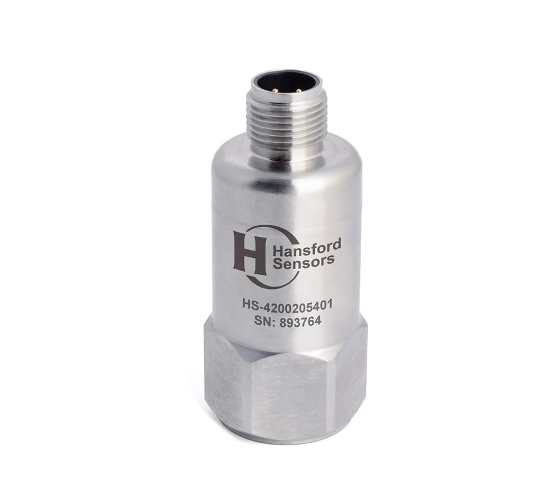
HS-420 4–20 mA vibration sensor (velocity), top exit, M12 connector
- 4–20 mA
- Top exit
- IP68
- M12
PDF datasheet
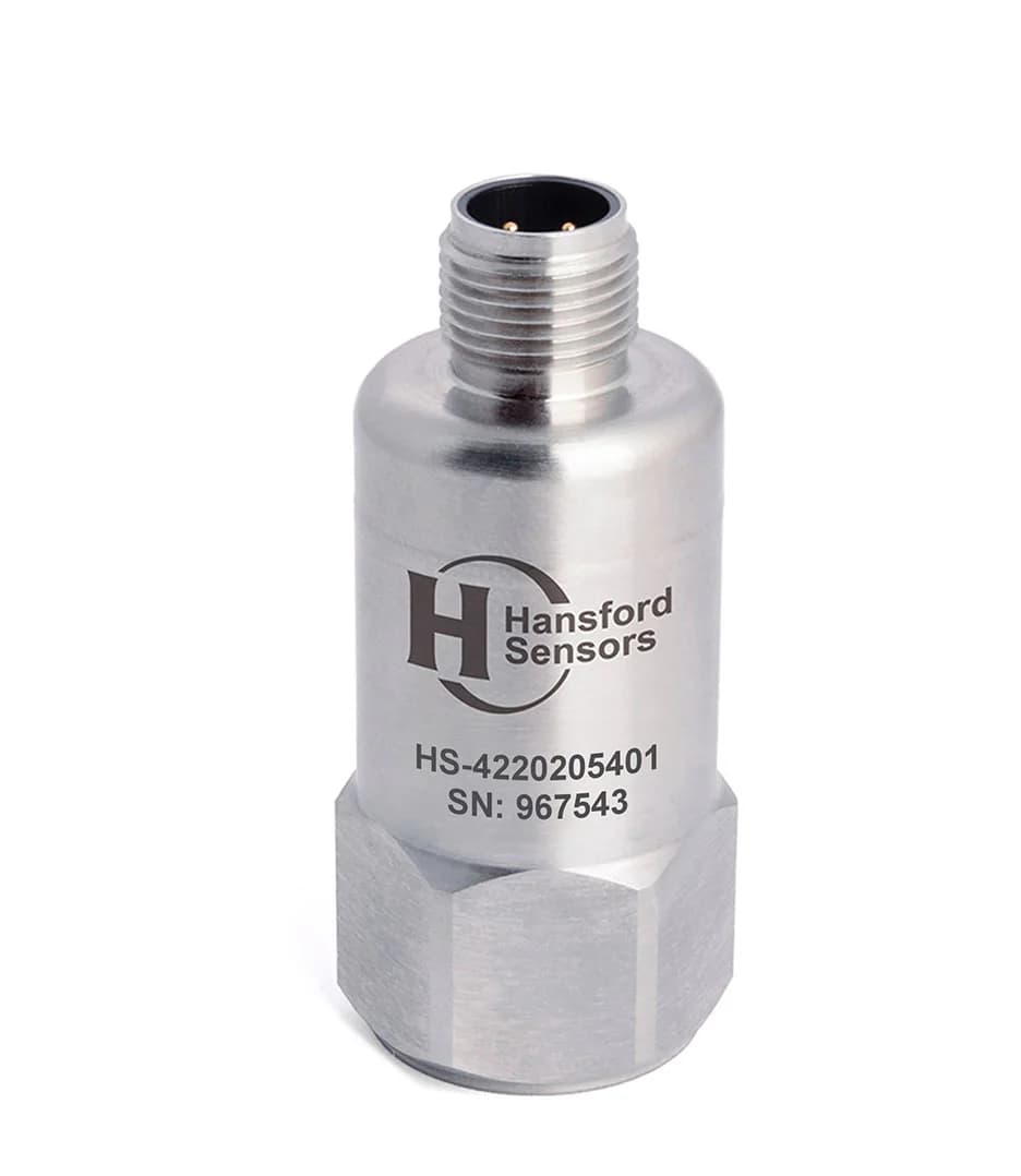
HS-422 4–20 mA vibration sensor (acceleration), top exit, M12 connector
- 4–20 mA
- Top exit
- IP68
- M12
PDF datasheet
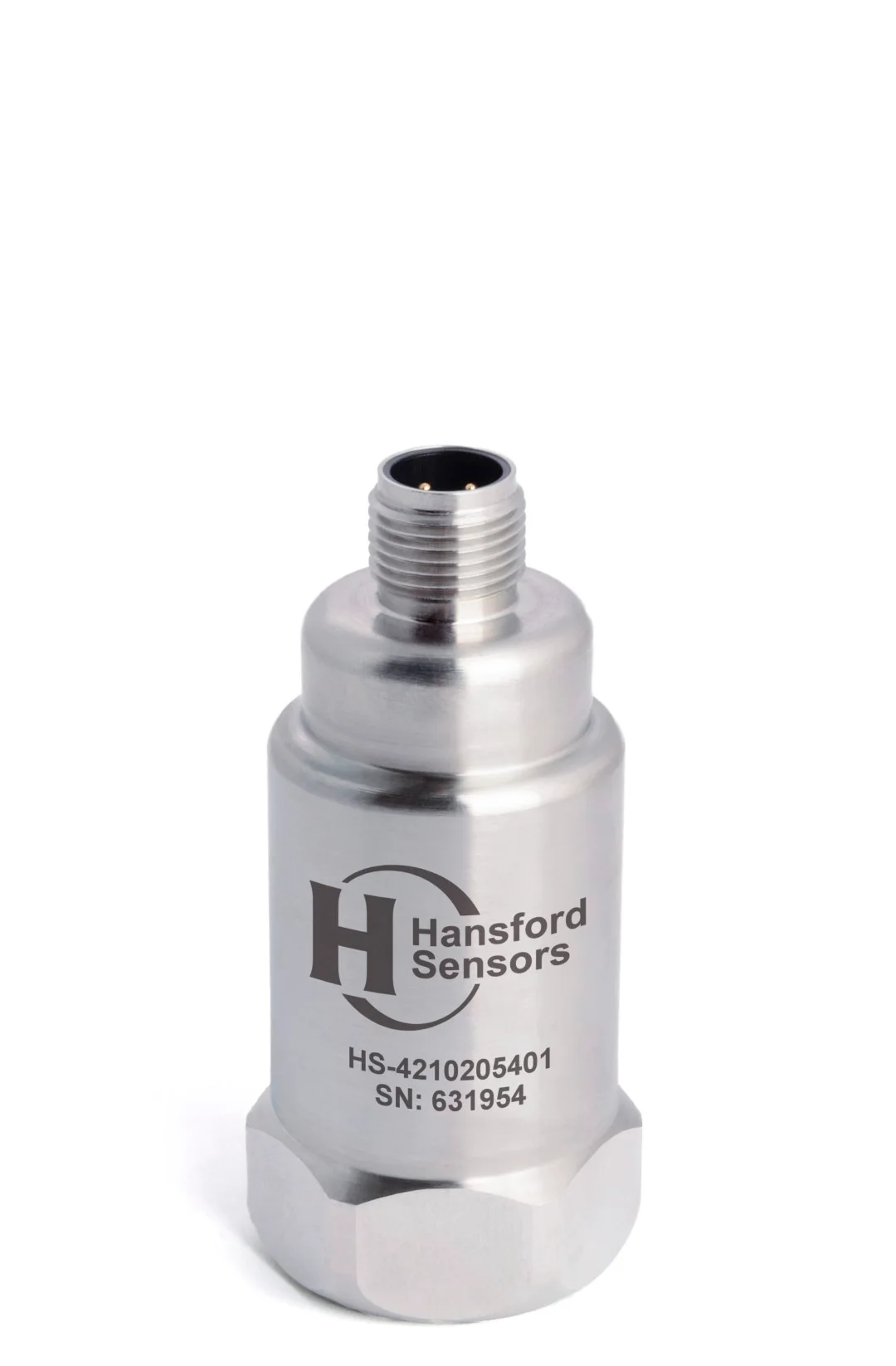
HS-421 4–20 mA vibration sensor (velocity) with additional AC output, top exit, M12 connector
- AC IEPE + 4–20 mA
- Top exit
- IP67
- M12
PDF datasheet
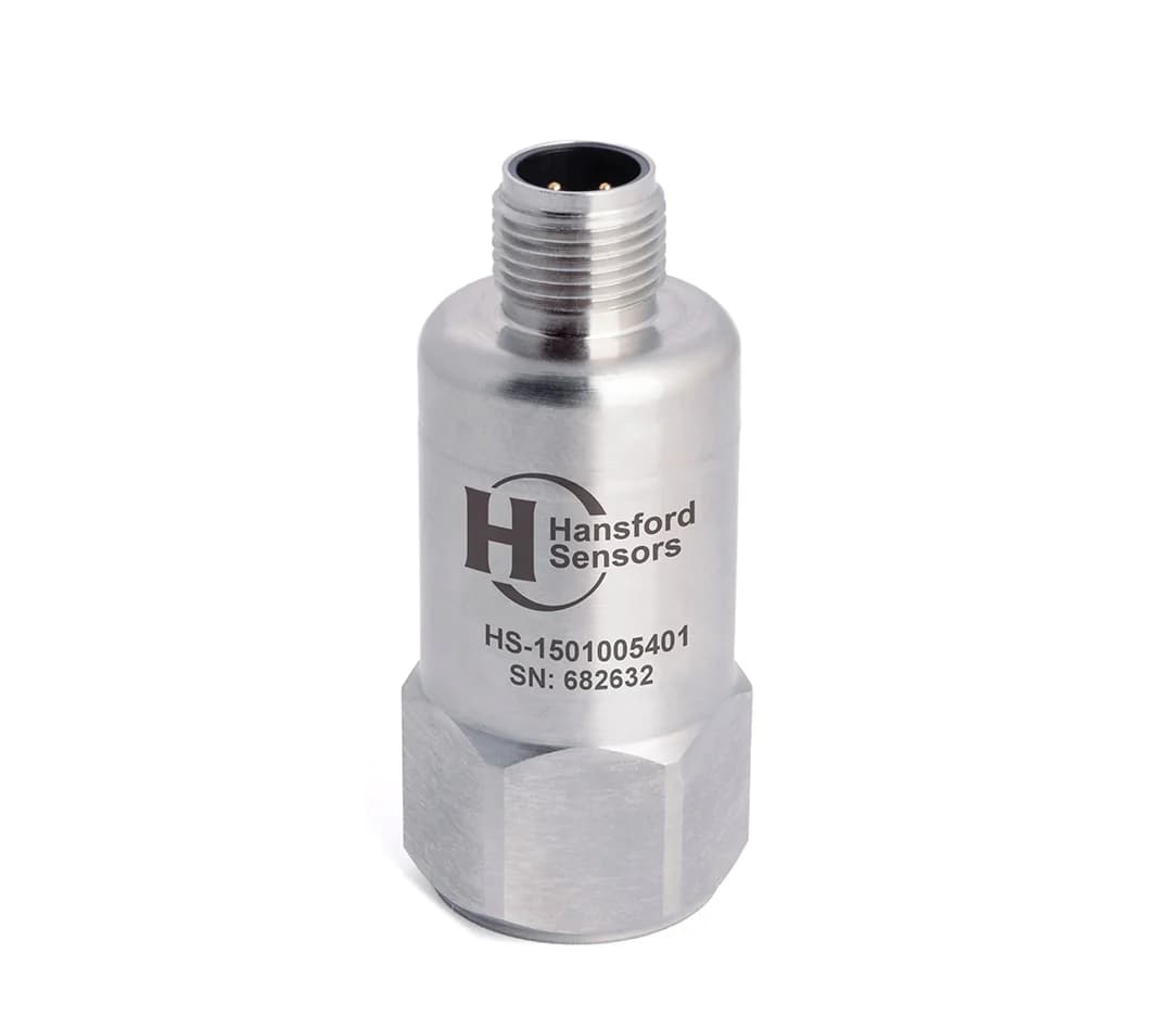
HS-150 Industrial AC accelerometer, top exit, M12 connector
- AC IEPE
- 100 mV/g
- Top exit
- M12
PDF datasheet
Related reading
Guide · Sensor selection · 6 min read
How to choose a vibration sensor for your machine
Choosing a vibration sensor starts with the question of where the signal will go. Step by step, we cover the output type, measured quantity, sensitivity, frequency range, operating conditions, connection type, mounting and number of axes — with a checklist at the end.
Guide · Sensor selection · 5 min read
IEPE accelerometer or 4–20 mA transmitter? A comparison
An IEPE accelerometer delivers the full vibration signal for analysis, while a 4–20 mA transmitter delivers a single overall value to the PLC. We explain how both types work, how they differ and when a dual-output sensor is worth using.
Guide · Mounting and installation · 5 min read
Mounting a vibration sensor: stud, adhesive or magnet?
The mounting method determines which frequencies the sensor can measure and whether successive measurements will be comparable. We compare studs, adhesive mounting pads and magnetic mounts, and cover surface preparation, measurement direction, cable routing and common mistakes.