GuideHazardous areas6 min read
Vibration sensors in Ex zones: a selection and installation guide
In a hazardous area, a vibration sensor is part of the explosion protection system, not just a measuring instrument. We explain zone classification, the principle of intrinsic safety, the role of barriers and what to check in the certificate and documentation.
Author: HS SensorsPublished Updated
In refineries, chemical and pharmaceutical plants, mines, mills or grain silos, a measurement point may be located where an explosive atmosphere is present or may occur. The vibration sensor, its cable and the entire measurement circuit then become part of the explosion protection system. This guide sets out the basic concepts — it does not, however, replace the certificate, the manufacturer’s instructions or a design prepared by a suitably qualified person.
Hazardous area zones
Zone classification is carried out by the end user of the installation on the basis of a risk assessment and recorded in the site documentation — in Poland, in the explosion protection document. The rules derive from Directive 1999/92/EC and national regulations. Zones are defined separately for gases and vapours, and for dusts.
Gases, vapours and mists
Zone 0 — an explosive atmosphere is present continuously, frequently or for long periods.
Zone 1 — an explosive atmosphere may occur occasionally in normal operation.
Zone 2 — an explosive atmosphere does not occur in normal operation and, if it does occur, persists for a short period only.
Combustible dusts
Zone 20 — a cloud of combustible dust in air is present continuously, frequently or for long periods.
Zone 21 — a dust cloud may occur occasionally in normal operation.
Zone 22 — a dust cloud does not occur in normal operation and, if it does occur, persists for a short period only.
Equipment groups, categories and protection levels
The ATEX Directive 2014/34/EU divides equipment into Group I — for underground parts of mines and their surface installations at risk from methane or coal dust — and Group II, covering all other locations. Within Group II, there are Categories 1, 2 and 3, marked G (gases) or D (dusts): Category 1 corresponds to Zones 0 and 20, Category 2 to Zones 1 and 21, and Category 3 to Zones 2 and 22. Category 1 equipment can also be used in zones intended for Categories 2 and 3, and Category 2 equipment also in zones for Category 3.
The IEC/EN 60079 series of standards, on which the IECEx system is also based, uses equipment protection levels (EPL): Ga, Gb, Gc for gases, Da, Db, Dc for dusts and Ma, Mb for mining. In addition, the following are specified: the gas group (IIA, IIB, IIC — IIC being the most demanding), the dust group (IIIA, IIIB, IIIC) and the temperature class T1–T6, which indicates the maximum surface temperature of the equipment. The higher the class number, the lower the permitted surface temperature.
The example marking Ex ia IIC T4 Ga reads as follows: Ex — explosion-protected equipment, ia — intrinsic safety at the highest level of protection, IIC — gas group, T4 — temperature class, Ga — equipment protection level suitable for Zone 0. The same sensor may have several lines of marking — for gases and for dusts, and for different ambient temperature ranges — so you must select the one that matches the conditions at the installation location.
Intrinsic safety (Ex i)
Intrinsic safety is based on limiting the electrical energy in a circuit — voltage, current and power, as well as the energy stored in capacitances and inductances — to a level that cannot ignite an explosive atmosphere, either by a spark or by surface heating. Unlike a flameproof enclosure, the aim is not to withstand an explosion but to prevent ignition from occurring at all. Level of protection ‘ia’ remains safe with two faults and is suitable for Zones 0 and 20; ‘ib’ remains safe with one fault (Zones 1 and 21); and ‘ic’ in normal operation (Zones 2 and 22).
An intrinsically safe sensor does not provide protection on its own. Only the complete circuit is safe: the sensor in the hazardous area, the cable and the associated apparatus — the barrier — located outside the hazardous area or in a suitable enclosure.
Zener barrier or galvanic isolator
A barrier limits the voltage and current that can reach the hazardous area, even if equipment on the safe-area side fails. Two types are used:
Zener barrier — a simple design with Zener diodes, a resistor and a fuse. It requires a reliable connection to an intrinsically safe earth and does not provide galvanic isolation.
Galvanic isolator — isolates the hazardous-area circuit from the safe-area circuit, does not require an intrinsically safe earth and reduces earth loop problems, but usually needs its own power supply.
Each measurement circuit requires its own barrier channel; several sensors must not share one channel. For multi-axis sensors and sensors with a temperature output, the number of channels and the wiring are specified in the certificate and the manufacturer’s instructions. The barrier must also suit the type of signal: for an IEPE accelerometer, it must pass the sensor supply current and the dynamic signal without excessive voltage drop or restriction of the frequency range; for a 4–20 mA transmitter, it must work with the current loop and the analogue input. The documentation library contains the manufacturer’s guides to safety barriers.
Matching sensor and barrier entity parameters
The sensor documentation gives its input parameters: Ui, Ii, Pi, Ci and Li; the barrier documentation gives its output parameters: Uo, Io, Po, Co and Lo. The circuit is valid when the following conditions are met:
Uo ≤ Ui, Io ≤ Ii, Po ≤ Pi,
Ci + cable capacitance ≤ Co,
Li + cable inductance ≤ Lo.
Cable capacitance and inductance increase with cable length, so every configuration has a maximum permissible cable length. The manufacturer publishes guides on maximum cable length for the intrinsically safe versions. Also check that the gas or dust group and the temperature class of both devices are suitable for the hazardous area, and that the sensor’s ambient temperature range covers the conditions at the installation location — taking into account the heat given off by the machine.
Other types of protection: Ex d and Ex tb
Ex d — flameproof enclosure — the enclosure withstands an internal explosion and prevents the flame from propagating to the outside. For vibration sensors, it is used, for example, as a flameproof connection head.
Ex tb — protection by enclosure — applies to dust zones: a sealed enclosure prevents dust from entering, and the surface temperature is limited. Level ‘tb’ corresponds to EPL Db, i.e. Zones 21 and 22.
The type of protection is selected by the installation designer. Each type has its own installation requirements, e.g. for cable glands and cable entries.
Documentation to check
Certificate — EU-type examination certificate (ATEX) or IECEx certificate of conformity. The letter ‘X’ at the end of the certificate number indicates special conditions for safe use, which are described in the certificate.
EU declaration of conformity — required for equipment placed on the European Union market.
Marking — on the equipment and in the datasheet: group, category or EPL, type of protection, gas or dust group, temperature class and ambient temperature range.
Instructions and system diagram — connection requirements, circuit parameters, recommendations on cables and earthing.
Datasheets, instructions and guides are available in the ‘Documentation’ section of the product page, and certificates and other manufacturer documents in the documentation library. Most of the manufacturer’s documents are in English.
Design, installation and measurement in the hazardous area
Installations in hazardous areas are designed and erected in accordance with EN 60079-14, and inspected and maintained in accordance with EN 60079-17. The work should be carried out by suitably qualified persons. If periodic measurements are to be taken in the hazardous area with a portable data collector, the data collector itself must also be approved for use in that zone. An alternative is to bring the sensor signals out to a readout point outside the hazardous area, in accordance with the intrinsically safe installation design. There are also intrinsically safe connection boxes designed for measurement circuits in Ex zones.
Intrinsically safe versions are available in the accelerometers for Ex zones and intrinsically safe 4–20 mA transmitters categories. The manufacturer offers them with ATEX certification, and some versions also with IECEx; the scope of approvals for a specific model is given in its specification and certificate.
Products in this article
Full catalogue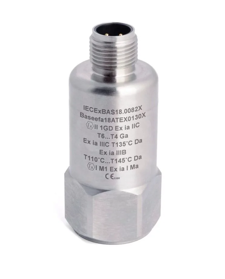
HS-100I Intrinsically safe accelerometer, top exit, M12 connector
- AC IEPE
- 10 … 100 mV/g
- Top exit
- IP67
PDF datasheet
HS-150I Intrinsically safe accelerometer, top exit, M12 connector
- AC IEPE
- 10 … 500 mV/g
- Top exit
- IP67
PDF datasheet
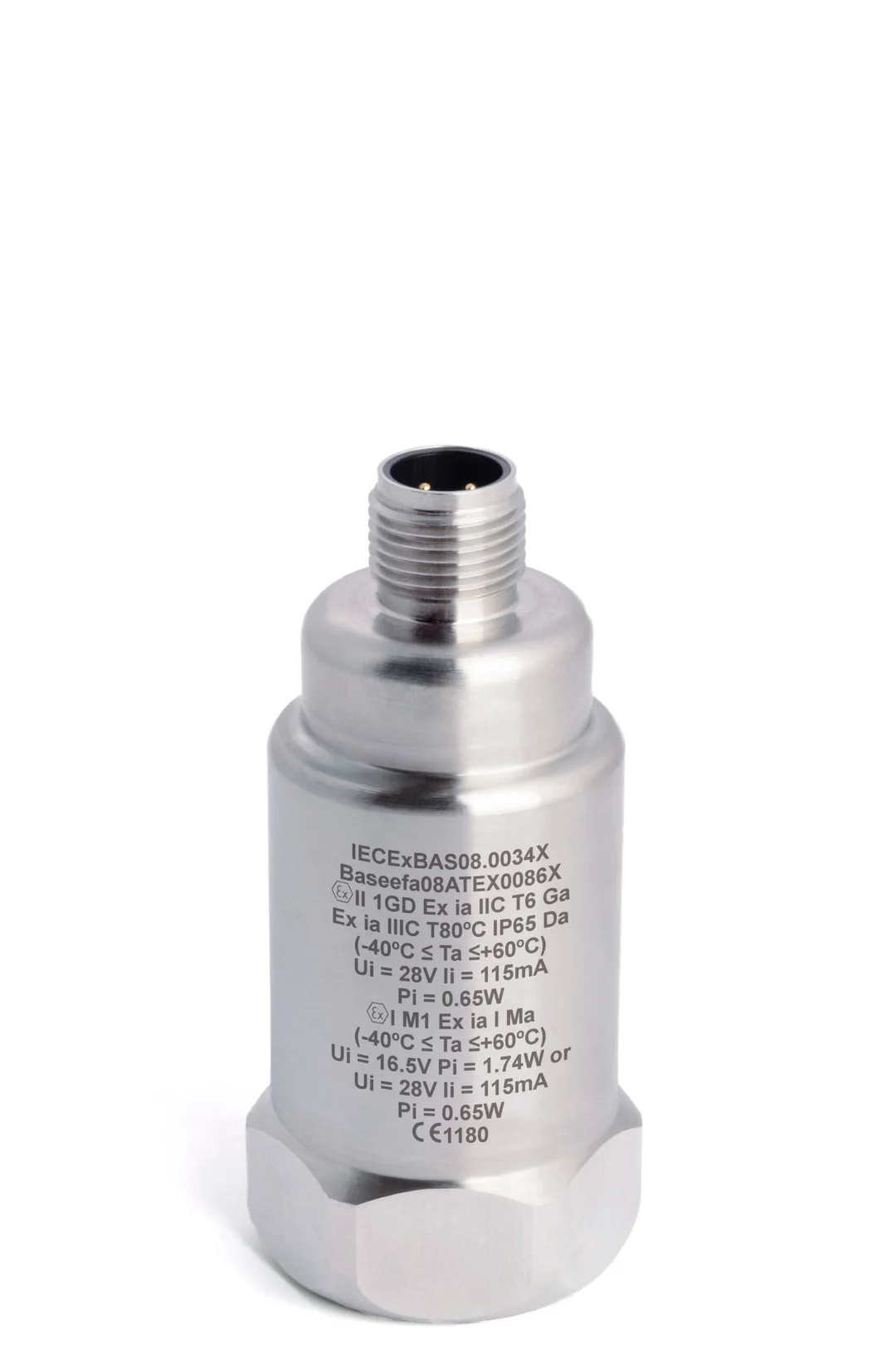
HS-420I/M Intrinsically safe 4–20 mA vibration sensor (velocity), top exit, M12 connector
- 4–20 mA
- Top exit
- IP67
- Ex i
PDF datasheet
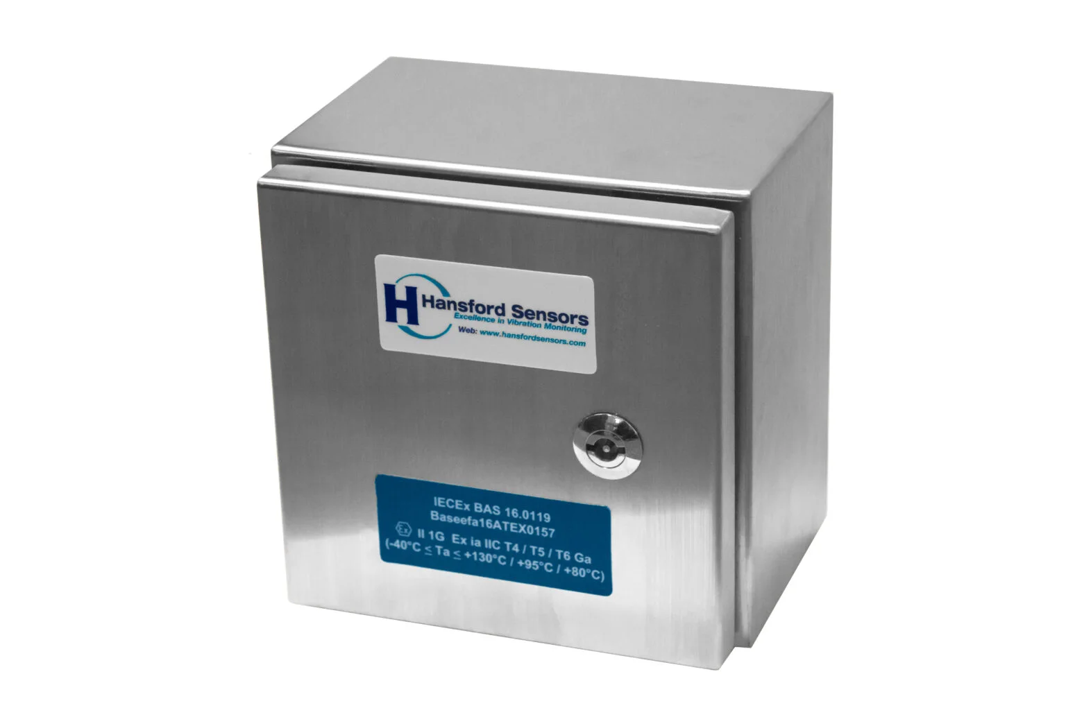
HS-ICE Intrinsically safe stainless steel connection box
- IP66
- Ex i
PDF datasheet
Related reading
Guide · Sensor selection · 6 min read
How to choose a vibration sensor for your machine
Choosing a vibration sensor starts with the question of where the signal will go. Step by step, we cover the output type, measured quantity, sensitivity, frequency range, operating conditions, connection type, mounting and number of axes — with a checklist at the end.
Guide · Sensor selection · 5 min read
IEPE accelerometer or 4–20 mA transmitter? A comparison
An IEPE accelerometer delivers the full vibration signal for analysis, while a 4–20 mA transmitter delivers a single overall value to the PLC. We explain how both types work, how they differ and when a dual-output sensor is worth using.
Guide · Mounting and installation · 5 min read
Mounting a vibration sensor: stud, adhesive or magnet?
The mounting method determines which frequencies the sensor can measure and whether successive measurements will be comparable. We compare studs, adhesive mounting pads and magnetic mounts, and cover surface preparation, measurement direction, cable routing and common mistakes.