GuideSensor selection5 min read
IEPE accelerometer or 4–20 mA transmitter? A comparison
An IEPE accelerometer delivers the full vibration signal for analysis, while a 4–20 mA transmitter delivers a single overall value to the PLC. We explain how both types work, how they differ and when a dual-output sensor is worth using.
Author: HS SensorsPublished Updated
Two types of sensor dominate industrial vibration monitoring: accelerometers with an IEPE-standard AC output, and loop-powered vibration transmitters with a 4–20 mA output. Both are mounted in the same way — on the bearing housing — but they deliver entirely different information and work with different equipment. In practice, choosing between them means deciding who will use the measurement results, and how.
How an IEPE accelerometer works
A piezoelectric element generates an electrical charge proportional to acceleration. Built-in electronics convert this charge into a voltage signal with low output impedance, which is much less susceptible to interference than the raw charge signal and allows longer cables to be used. The abbreviation IEPE (Integrated Electronics Piezo-Electric) refers to the way these electronics are powered: the sensor draws a constant current from the measuring instrument over the same pair of wires that carries the signal.
The sensor output carries a DC bias voltage with the AC vibration signal superimposed on it. The instrument input removes the DC component and processes only the AC component. The bias voltage also has a diagnostic function: a marked change in it indicates an open circuit, a short circuit or a sensor fault, which is why many systems and testers monitor it continuously.
An IEPE accelerometer therefore needs a powered input, as found on data collectors, vibration analysers, online monitoring systems and DIN-rail power supply modules. A standard PLC analogue input will neither power the sensor nor process the fast-changing signal.
The standard sensitivity of AC accelerometers is 100 mV/g, and the manufacturer’s standard frequency range is 0.8 Hz – 15 kHz (±3 dB). From this signal, the instrument derives the time waveform, FFT spectrum, envelope, RMS and peak values and, after integration, vibration velocity.
How a 4–20 mA vibration transmitter works
A 4–20 mA vibration transmitter (loop-powered sensor, LPS) also contains a piezoelectric element, but its electronics convert the vibration directly into a single overall value: RMS vibration velocity in mm/s or acceleration in g. The measuring range is selected when ordering, e.g. 0–25 mm/s: 4 mA corresponds to zero and 20 mA to full scale.
The transmitter is powered from the current loop, and the same two wires carry both power and signal. It is connected to a 4–20 mA analogue input of a PLC, DCS or SCADA system, or to a display or relay module. The current signal is immune to voltage drops along long cables and relatively insensitive to interference, and the ‘live zero’ makes faults easy to detect: a current well below 4 mA indicates an open circuit or loss of power.
The price of this simplicity is the lack of frequency information. A 4–20 mA signal shows how much the machine is vibrating, but not why. An increase in the overall value may be caused by unbalance, looseness, misalignment or bearing damage — telling these apart requires analysis of the dynamic signal.
Point-by-point comparison
Output signal
IEPE — dynamic voltage signal proportional to acceleration.
4–20 mA — current proportional to the overall velocity or acceleration value within the selected range.
Power supply
IEPE — constant current from the instrument or module, supplied over the signal cable.
4–20 mA — from the current loop, e.g. from an analogue input card or a loop power supply.
Receiving equipment
IEPE — data collector, analyser, online monitoring system, module with IEPE power supply.
4–20 mA — PLC, DCS, SCADA, BMS, display or alarm module.
Diagnostic information
IEPE — full: the spectrum, envelope and time waveform make it possible to identify the cause of the vibration.
4–20 mA — trending and alarms; the cause has to be established by separate analysis.
Configuration
IEPE — sensitivity depends on the model and version (100 mV/g as standard); the frequency range and signal processing are set in the instrument.
4–20 mA — measured quantity (velocity or acceleration) and measuring range are selected when ordering.
Cabling
IEPE — screened cable; with very long cables, cable capacitance can limit the transmission of high frequencies, so check the recommendations in the datasheet.
4–20 mA — standard instrumentation cabling and typical analogue inputs.
When to choose an IEPE accelerometer
When you run a vibration diagnostics programme with measurement routes and a portable data collector.
When the machine is covered by an online monitoring system that analyses spectra and envelopes.
When you need to detect early-stage damage to rolling-element bearings and gearboxes.
When the measurement should identify the cause of a problem, not just its occurrence.
When to choose a 4–20 mA transmitter
When vibration needs to be visible in the control system alongside other process signals.
When you need warning and alarm thresholds or machine shutdown.
When you monitor many simpler machines — fans, pumps, compressors — without ongoing diagnostic support.
When the signal has to be transmitted over a long distance to existing instrumentation infrastructure.
Points to watch during implementation
4–20 mA range — once full scale is exceeded, the signal stops rising, so the system will not show how much higher the vibration is. Conversely, an overly wide range reduces resolution in the region of typical values.
Measurement frequency range — a 4–20 mA transmitter determines the overall value within the frequency range specified in its datasheet. A portable instrument with different filter settings may show a different value, even though both measurements are correct.
Loop supply — the supply voltage must cover the transmitter’s minimum operating voltage plus the voltage drops across the load resistance and the cables; the datasheet gives the limit values.
IEPE input — before connecting the accelerometer, check that IEPE power is enabled on the instrument or module. Without it, the sensor will not work and the readings will be close to zero.
Dual-output sensors
The choice does not have to be either/or: 4–20 mA transmitters with an additional AC output, such as the HS-421, send vibration velocity to the PLC and, in parallel, provide an AC acceleration signal that can be wired to a connection box and read with a data collector during periodic measurements. This adds full analysis to the overall value in the PLC — without an additional measurement point.
The second signal can also be temperature: 4–20 mA transmitters with temperature output have an additional 10 mV/°C or PT100 output, while accelerometers with temperature output combine the AC signal with temperature measurement. There are also sensors with three outputs: 4–20 mA, AC and temperature.
Another option is an IEPE accelerometer connected to a DIN-rail module. In the monitoring systems category, you will find modules that power IEPE sensors, as well as modules that convert the accelerometer signal into a 4–20 mA output for the PLC and provide a buffered AC output for data collection.
If you are not sure which version suits your installation, use the sensor selector or our guide on how to choose a vibration sensor for your machine.
Products in this article
Full catalogue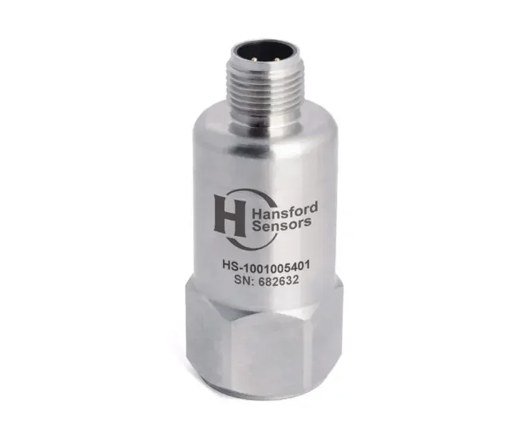
HS-100 Industrial AC accelerometer, top exit, M12 connector
- AC IEPE
- 10 … 500 mV/g
- Top exit
- IP67
PDF datasheet
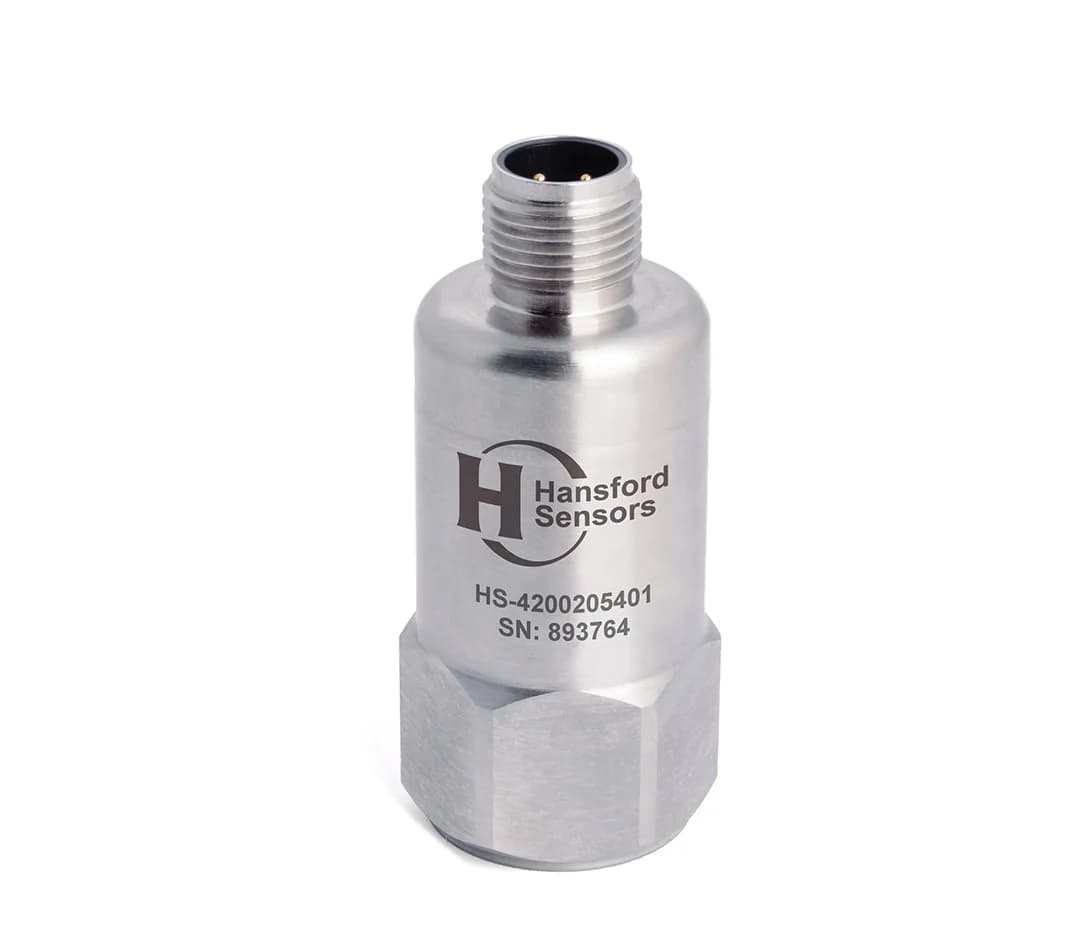
HS-420 4–20 mA vibration sensor (velocity), top exit, M12 connector
- 4–20 mA
- Top exit
- IP68
- M12
PDF datasheet
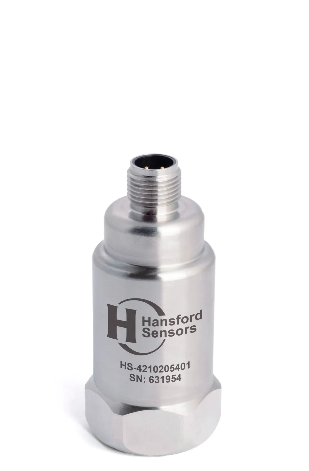
HS-421 4–20 mA vibration sensor (velocity) with additional AC output, top exit, M12 connector
- AC IEPE + 4–20 mA
- Top exit
- IP67
- M12
PDF datasheet
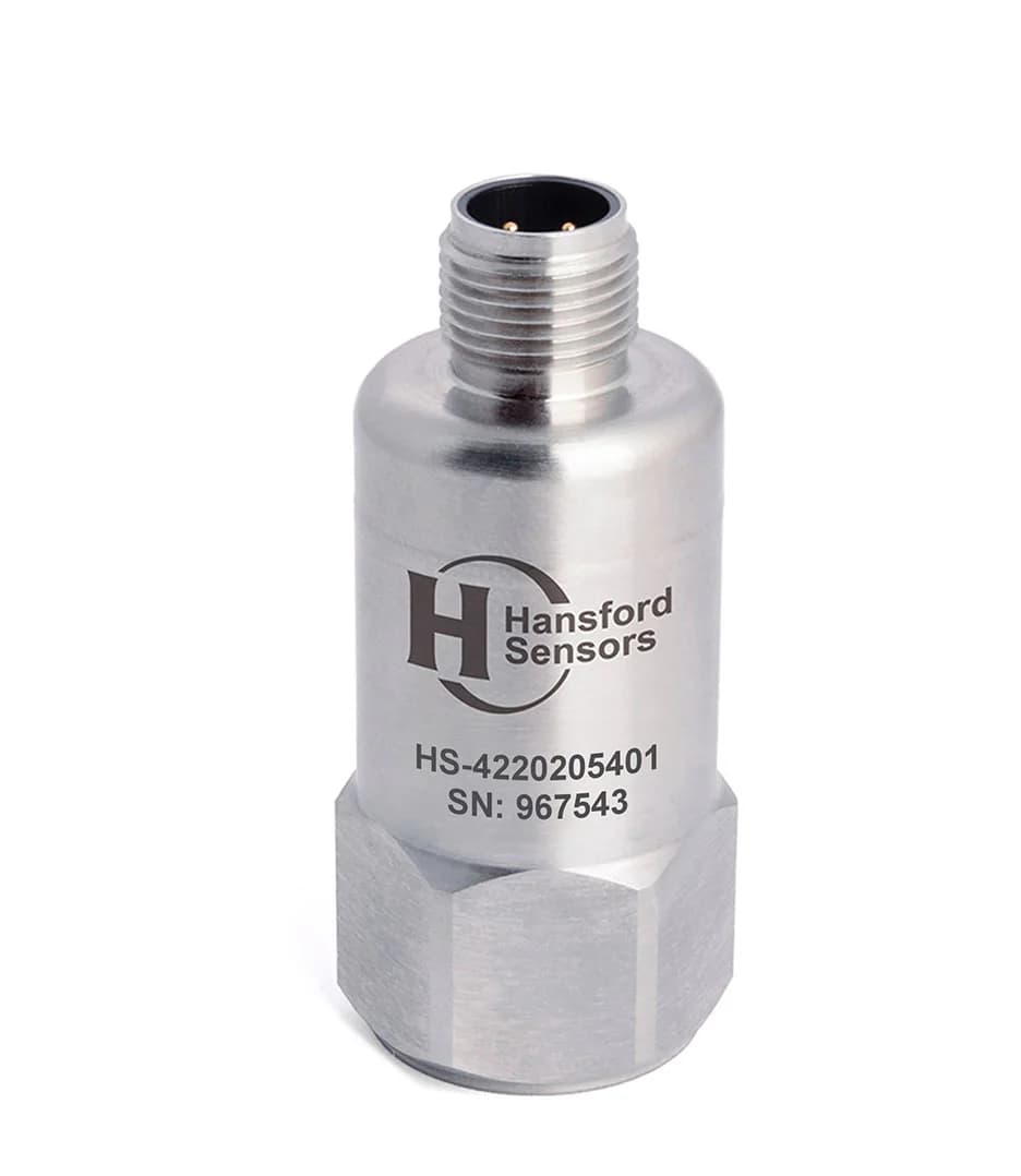
HS-422 4–20 mA vibration sensor (acceleration), top exit, M12 connector
- 4–20 mA
- Top exit
- IP68
- M12
PDF datasheet
Related reading
Guide · Sensor selection · 6 min read
How to choose a vibration sensor for your machine
Choosing a vibration sensor starts with the question of where the signal will go. Step by step, we cover the output type, measured quantity, sensitivity, frequency range, operating conditions, connection type, mounting and number of axes — with a checklist at the end.
Guide · Mounting and installation · 5 min read
Mounting a vibration sensor: stud, adhesive or magnet?
The mounting method determines which frequencies the sensor can measure and whether successive measurements will be comparable. We compare studs, adhesive mounting pads and magnetic mounts, and cover surface preparation, measurement direction, cable routing and common mistakes.
Guide · Hazardous areas · 6 min read
Vibration sensors in Ex zones: a selection and installation guide
In a hazardous area, a vibration sensor is part of the explosion protection system, not just a measuring instrument. We explain zone classification, the principle of intrinsic safety, the role of barriers and what to check in the certificate and documentation.