GuideMounting and installation5 min read
Mounting a vibration sensor: stud, adhesive or magnet?
The mounting method determines which frequencies the sensor can measure and whether successive measurements will be comparable. We compare studs, adhesive mounting pads and magnetic mounts, and cover surface preparation, measurement direction, cable routing and common mistakes.
Author: HS SensorsPublished Updated
Even a well-chosen sensor can only measure what reaches it through its connection to the machine. The sensor and its mounting form a mechanical system with its own resonant frequency — the less rigid the connection and the greater the mass of the intermediate parts, the lower the resonance and the narrower the usable frequency range. Poor mounting can also introduce components into the signal that do not originate in the machine, and make successive measurements impossible to compare.
The datasheet specifies the sensor’s characteristics for a reference mounting method, usually stud mounting. Any other method narrows the frequency range to an extent that depends on its stiffness and on the condition of the surface.
Stud mounting
Mounting on a threaded stud in a prepared tapped hole gives the stiffest connection and the widest usable frequency range. It is the standard method for permanent installations and for measurements in which high frequencies matter, e.g. in rolling-element bearing and gearbox diagnostics.
Correct mounting requires several conditions to be met:
Flat, smooth surface — the sensor base must be in contact with the machine over its entire area. On castings and on painted or uneven surfaces, the mounting surface is spot faced.
Hole perpendicular to the surface — the thread axis must be perpendicular to the spot-faced surface; otherwise the sensor will rest on one edge and the connection will lose stiffness.
Adequate hole depth — the stud must not bottom out in the hole, because the sensor will then not seat firmly against the surface.
Correct thread — matching the sensor thread (e.g. 1/4"-28 UNF, M6, M8 or M10); adaptor studs are used where necessary.
Thin layer of coupling grease — it fills microscopic surface irregularities and improves the transmission of high frequencies. It should fill the gaps, not act as a spacer.
Mounting torque as specified in the datasheet — under-tightening reduces the stiffness of the connection, while over-tightening risks damaging the thread and may affect the sensor’s performance. Use a torque wrench.
The mounting point is prepared with spot-facing tools. A spot-facing cutter produces a flat surface perpendicular to the axis of the hole; the spot-facing kit is portable, comes in versions for different mounting threads and is used with a hand-held drill. Where the sensor housing has to be electrically isolated from the machine earth, e.g. to avoid earth loops, isolation studs are used.
Adhesive mounting pads
When drilling is not an option — because of thin walls, warranty restrictions imposed by the machine manufacturer or because machining is not possible — a mounting pad is bonded to the surface and the sensor is screwed onto it in the same way as onto a stud. The sensor can later be removed without disturbing the bond.
Remove paint, rust and dirt, degrease the surface and abrade it if necessary.
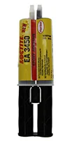
Use a rigid adhesive intended for this purpose, e.g. a two-part adhesive for mounting pads, applied in a thin layer.
Observe the curing time and the permissible operating temperature stated in the adhesive’s datasheet.
Avoid soft, thick bonds such as silicone or double-sided tape — they attenuate high frequencies.
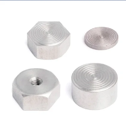
The mounting studs and pads category contains adhesive, conical and Quick Fit pads, isolation studs and adaptors, also in versions for triaxial sensors.
Magnetic mounts
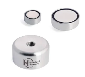
Magnetic mounts are used for periodic measurements with a portable data collector or vibration meter — they let you move the sensor quickly from point to point along a route. The catalogue includes flat-face magnets and pole-piece magnets in several diameters, with different holding forces and threads.
A magnet adds mass and forms a less rigid connection than a stud, so it lowers the sensor’s mounted resonance and reduces the upper limit of the usable frequency range. In practice, this means poorer transmission of the high-frequency components that are important in bearing and gearbox diagnostics. The size of this effect depends on the magnet, the sensor and the surface condition — check it in the datasheets of both the magnet and the sensor.
The magnet base must sit flush on the surface over the whole contact area. On a curved surface, e.g. a motor casing, a flat-face magnet makes only partial contact, which impairs vibration transmission and mounting stability — choose a magnet that matches the shape of the surface or prepare a flat measurement point.
Place the magnet on a clean surface, free from flaking paint and rust; a thin layer of coupling grease improves vibration transmission.
Do not let the magnet strike the surface — bring it into contact at an angle and ease it into place. An impact can exceed the sensor’s shock limit and disturb the measurement.
After attaching the magnet, wait for the signal to settle, especially when measuring low frequencies.
Mark the measurement points on the machine so that each measurement is taken at the same location and in the same direction. Permanently bonded measurement points made of ferromagnetic material are also used for this purpose.
A magnet is no substitute for permanent mounting — for a permanent installation, especially on machines with high vibration levels, choose a stud or an adhesive mounting pad. For quick, indicative measurements in places that are difficult to reach, a probe tip (stinger) held against the machine by hand is also used; of the methods described, it gives the narrowest frequency range and the lowest repeatability, so it is not suitable for trending.
Measurement direction and location
Mount the sensor as close to the bearing as possible, on a rigid part of the housing through which vibration passes directly from the bearing.
Avoid guards, sheet-metal covers and fan cowls — they have their own resonances and transmit the bearing signal poorly. Do not mount the sensor directly on a single cooling fin; on finned housings, purpose-made fin mounts are used.
On horizontal machines, measure radially as a rule — horizontally and vertically — and also axially where necessary; the axial direction helps to detect faults such as misalignment.
Keep the same point, direction and mounting method for successive measurements — only then is the trend reliable.
With triaxial sensors, pay attention to the orientation of the axes; an axis alignment adaptor helps with this.
Record the position and direction of each sensor in the measurement point documentation.
Cable routing
Secure the cable with a cable tie or clamp close to the sensor so that it cannot vibrate freely or put strain on the connector.
Leave a small strain-relief loop; positioned below the connector, it also helps water to drain away before reaching the connection.
Do not bend the cable sharply where it leaves the sensor — observe the minimum bend radius.
Route signal cables away from power cables and inverter output cables; where they have to cross, they should cross at right angles.
Where there is a risk of damage, use braided cable or protective conduit.
Connect the cable screen to earth as specified in the sensor and system documentation — usually at one point only, to avoid earth loops.
Label cables at both ends.
Most common mistakes
Mounting on an uneven, painted or corroded surface without spot facing.
A hole drilled at an angle or too shallow — the stud bottoms out and the sensor does not sit flush.
Tightening ‘by feel’ instead of to the torque given in the datasheet.
No coupling grease, or too thick a layer of adhesive.
Mounting the sensor on a guard or thin sheet metal instead of on the bearing housing.
A cable hanging loose or under tension at the connector.
Changing the measurement point, direction or mounting method between measurements.
Using an adhesive, magnet or cable outside its permitted temperature range.
After installation, it is worth checking the sensor and cable — an accelerometer tester lets you verify that the sensor and cable are working and check the bias voltage before the system is put into operation. Installation instructions for studs and pads are available on the product pages and in the documentation library.
Products in this article
Full catalogue
Related reading
Guide · Sensor selection · 6 min read
How to choose a vibration sensor for your machine
Choosing a vibration sensor starts with the question of where the signal will go. Step by step, we cover the output type, measured quantity, sensitivity, frequency range, operating conditions, connection type, mounting and number of axes — with a checklist at the end.
Guide · Sensor selection · 5 min read
IEPE accelerometer or 4–20 mA transmitter? A comparison
An IEPE accelerometer delivers the full vibration signal for analysis, while a 4–20 mA transmitter delivers a single overall value to the PLC. We explain how both types work, how they differ and when a dual-output sensor is worth using.
Guide · Hazardous areas · 6 min read
Vibration sensors in Ex zones: a selection and installation guide
In a hazardous area, a vibration sensor is part of the explosion protection system, not just a measuring instrument. We explain zone classification, the principle of intrinsic safety, the role of barriers and what to check in the certificate and documentation.